


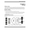

ZyWALL 2 and ZyWALL 2WE
Hardware Specifications 33
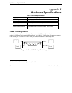
Chart I-2 Console/Dial Backup Port Pin Assignments
CONSOLE Port RS – 232 (Female) DB-9F DIAL BACKUP RS – 232 (Male) DB-9M
Pin 1 = NON
Pin 2 = DCE-TXD
Pin 3 = DCE –RXD
Pin 4 = DCE –DSR
Pin 5 = GND
Pin 6 = DCE –DTR
Pin 7 = DCE –CTS
Pin 8 = DCE –RTS
PIN 9 = NON
Pin 1 = NON
Pin 2 = DTE-RXD
Pin 3 = DTE-TXD
Pin 4 = DTE-DTR
Pin 5 = GND
Pin 6 = DTE-DSR
Pin 7 = DTE-RTS
Pin 8 = DTE-CTS
PIN 9 = NON.
The CON/AUX port also has these pin
assignments. The CON/AUX switch changes the
setting in the firmware only and does not change
the CON/AUX port’s pin assignments.
ZyWALLs with a CON/AUX port also have a 9-pin
adaptor for the console cable with these pin
assignments on the male end.
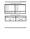
Chart I-3 Ethernet Cable Pin Assignments
WAN/LAN Ethernet Cable Pin Layout:
Straight-Through
Crossover
(Switch)
1 IRD +
(Adapter)
1 OTD +
(Switch)
1 IRD +
(Switch)
1 IRD +
2 IRD - 2 OTD - 2 IRD - 2 IRD -
3 OTD + 3 IRD + 3 OTD + 3 OTD +
6 OTD - 6 IRD - 6 OTD - 6 OTD -