11
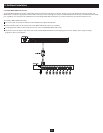
8. Multilevel Installation
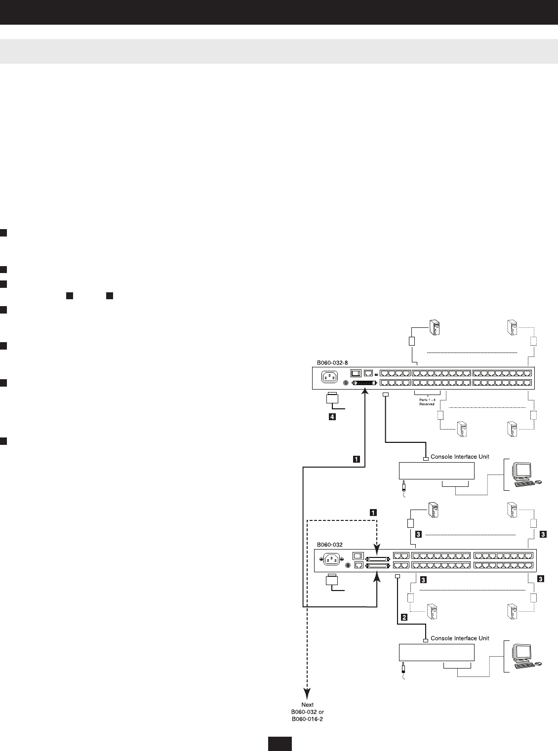
8.2 Daisy-Chaining*
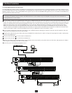
Up to seven B060-032 or B060-016-2 Matrix KVM Switches can be daisy-chained to the fi rst-level B060-032-8. When daisy chained with the B060-032 or
B060-016-2, the B060-032-8 must occupy the master (fi rst-level) position, while the B060-032 or B060-016-2 must be used as the slave KVM switch(es)
(those KVM switches daisy-chained from the master KVM switch).
When daisy-chaining B060-032 or B060-016-2 KVM switches, KVM Ports 1–4 on the fi rst-level B060-032-8 will be unusable. Neither computers nor
cascaded KVM switches can be connected to these KVM ports.
The B060-032-8 is capable of supporting eight independent KVM consoles, while each B060-032 or B060-016-2 is capable of supporting four or two
independent KVM consoles. In a complete daisy-chained installation, the eight KVM consoles that belong to the B060-032-8 can access and control all
of the computers on the installation; however, only four users can access the B060-032 simultaneously and only two users can access the B060-016-2
simultaneously. Any local KVM consoles connected to a daisy-chained B060-032 or B060-016-2 KVM switch control only the computers connected to their
respective KVM switches.
* If the daisy-chaining feature is not operational, your unit requires updated fi rmware. Contact your dealer for assistance or check for the latest fi rmware in the Support Section at www.tripplite.com.
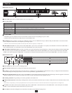
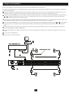
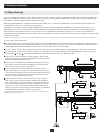
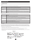
To set up a daisy-chained installation:
Use a daisy-chain cable* to connect the CHAIN OUT port of the master B060-032-8 to the CHAIN IN port of the slave B060-032 or B060-016-2. The
maximum distance between any two B060-032 or B060-016-2 KVM switches cannot exceed 33 ft. (10m). The maximum distance between the fi rst-level
(master) B060-032-8 and the last B060-032 or B060-016-2 in the daisy-chain cannot exceed 66 ft. (20m).
Use Cat5 cables to connect Console Interface Units (CIUs) to the consoles to be attached to the daisy-chained B060-032 or B060-016-2 KVM Switch.
Use Cat5 cables to connect a Server Interface Unit (SIU) to each computer/server to be attached to the daisy-chained B060-032 or B060-016-2 KVM
Switch. Repeat through for any additional B060-032 or B060-016-2 KVM Switches to be added to the chain.
Plug the power cords into a Tripp Lite Surge Suppressor, PDU or UPS
System, and into the power sockets on the B060-032-8 and daisy-chained
B060-032 or B060-016-2 KVM Switches.
Power on the master B060-032-8 KVM Switch and wait one minute for
the switch to ascertain its position. (The B060-032-8 has no station ID
since it always occupies the fi rst station position.)
Power on each KVM switch in the installation in sequence (second
station, third station, etc.). In each case, wait one minute for the position
to be determined and displayed on the current station ID before powering
on the next station. (The ID for the second-level KVM switch is 02, the
ID for the third-level KVM switch is 03, etc.)
After all the KVM switches are powered on, power on the computers.
Note: If you experience mouse interference problems after attaching a
local Console Interface Unit (CIU) to a daisy-chained KVM Switch, the
daisy-chained switches’ Broadcast mode may be enabled; if so it must
be turned off. You can do this inside the daisy-chained KVM switches’
OSD by pressing F6. After pressing F6, switch to another port. (Broadcast
Mode On/Off will not take effect until ports are switched.)
* If the daisy-chain cable included with the B060-016-2 or B060-032 is not long enough, use an
appropriate Tripp Lite P770-series cable.
1
2
1
3
3
4
5
6
7