6
6. Rackmounting
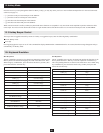
Stacking and Rackmounting
• The included rackmounting kit does not contain screws or cage nuts for attaching the B060-032-8 to your rack. If you need additional screws or cage nuts,
contact your rack dealer.
• Allow at least 2 in. (5.1cm) on each side for adequate ventilation and 5 in. (12.7cm) at the rear for power cord and cable clearance.
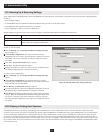
Rackmounting Safety Instructions
• Prior to installation, ensure that stabilizers are secured to the rack, extended to the fl oor, and that the full weight of the rack rests on the fl oor. Install front
and side stabilizers on a single rack or front stabilizers for joined multiple racks before working on the rack.
• Always load the rack from the bottom up, and load the heaviest item in the rack fi rst.
• Make sure that the rack is level and stable before extending a device from the rack.
• Do not overload the AC supply branch circuit that provides power to the rack. The total rack load should not exceed 80% of the branch circuit rating.
• Make sure that all rack equipment, including power strips and other electrical connectors, is properly grounded.
• Ensure that proper airfl ow is provided to devices in the rack.
• Ensure that the operating ambient temperature of the rack environment does not exceed the maximum ambient temperature specifi ed for the equipment by
the manufacturer (0° to 50° Celsius, 32° to 122° Fahrenheit).
• Do not step on or stand on any device when servicing other devices in a rack.
Stacking
The B060-032-8 can be placed on any level surface that will safely support its weight plus the weight of attached cables. Ensure that the surface is clean and
free of materials that could block the exhaust vents or otherwise interfere with normal operation of the unit. A foot pad set is included with the unit. Peel the
protective backing off of the foot pads and affi x them to the corners of the bottom panel of the unit.
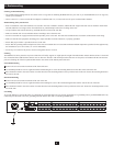
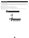
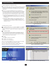
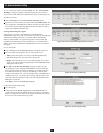
Front Rackmounting
Remove the screws located on each side of the front of the unit.
Use the Phillips head hex screws supplied with the rackmounting kit to screw the mounting brackets into the sides at the front of the unit.
Place the KVM switch in the rack. Position it so that the holes in the mounting brackets line up with the holes in the rack. Secure the mounting brackets to
the front of the rack.
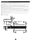
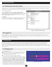
Rear Rackmounting
Remove the screws located on each side of the rear of the unit.
Use the Phillips head hex screws supplied with the rack mounting kit to screw the rack mounting brackets into the sides at the rear of the unit.
Place the KVM switch in the rack. Position it so that the holes in the mounting brackets line up with those in the rack. Secure the mounting brackets to the
rear of the rack.
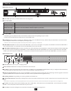
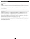
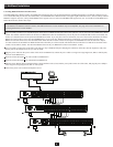
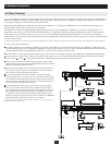
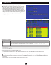
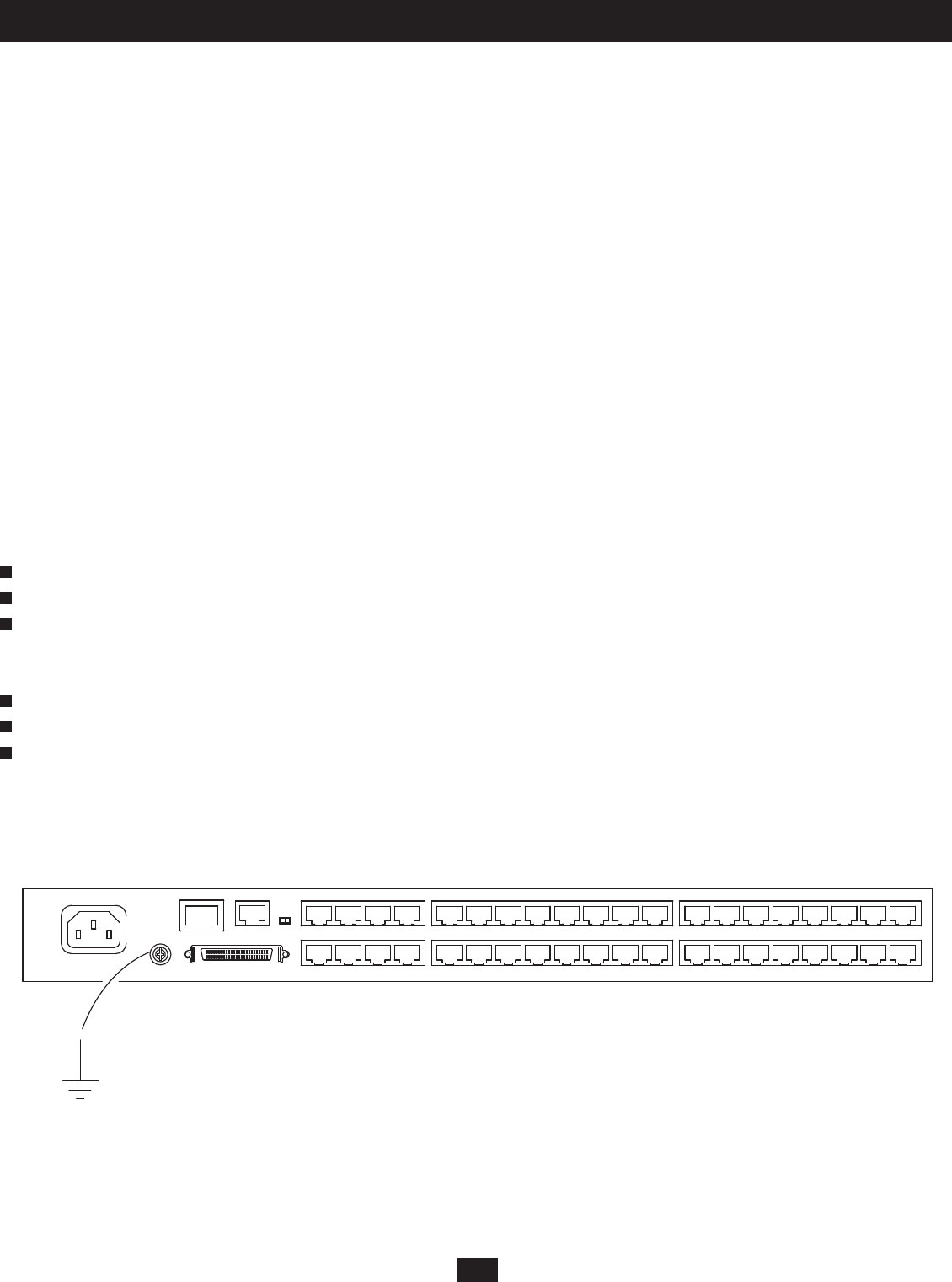
Grounding
To prevent damage to your KVM switch, it is important to ensure that all devices are properly grounded. Use a grounding wire to ground the B060-032-8 by
connecting one end of the wire to the grounding terminal and the other end to a suitable grounded object.
1
1
2
2
3
3