Major Chips Description 2-93
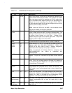
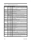
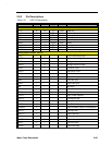
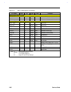
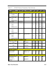
Table 2-17 T62.062.C Electrical Characteristics Table (Continued)
Parameter Symbol Condition MIN TYP MAX UNITS
OUTPUT
AC Source input Signal
(Voltage)
(Supply current)
AD5V AC source voltage >
8V
4.5 5 5.25
10
V
mA
Battery in use (High)
(Low)
(Supply current)
BAT-IN-USE# @I load=100uA 2.7 5 5.25
0.7
100
V
V
uA
Power Output DCBAT OUT - - 3 A
Charge Indicator
(High)
(Low)
(Supply current)
BT-QCHG Quick
3.5
-
-
5
-
-
5.25
0.8
100
V
V
uA
Battery Low 1
(High)
(Low)
(Supply Current)
BL1# @I load=100uA
2.7
-
-
5
-
-
5.25
0.7
100
V
V
uA
Battery Low 2
(High)
(Low)
(Supply Current)
BL2# @I load=100uA
2.7
-
-
5
-
-
5.25
0.7
100
V
V
uA
BATTERY LOW VOLTAGE WARNING SIGNAL
Battery Low 1 (NiMH)
(LIB)
@25
TC125PPM/
10.53
8.50
10.70
8.65
10.86
8.80
V
Battery Low 2 (NiMH)
(LIB)
@25
TC125PPM/
10.19
8.08
10.35
8.23
10.50
8.38
V
Battery Low 3 (NiMH)
(LIB)
@25
TC125PPM/
9.07
7.58
9.22
7.73
9.36
7.88
V
CHARGE PARAMETER
External Adapter
Charge current
System not in use
System in use
1.8
0.58
1.9
0.65
2.0
0.72
A
A
DC OPERATION (@25 Vin=10.8V)
Total Module Current
Consumption
( output pin not
included)
System on
System off
2.3
150
mA
uA


