


51
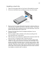
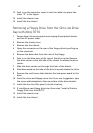
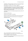
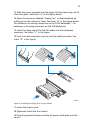
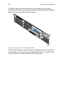
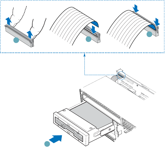
13.Slide the carrier assembly into the upper left hard drive bay until it
clicks into place. See letter "A" in the figure below.
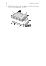
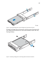
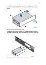
14.Open the connector labeled "Floppy Con" on the backplane by
pulling up on the connector cover. See letter "B" in the figure below.
For assistance in locating connectors on the SATA backplane." For
assistance in locating connectors on the SCSI backplane.
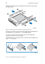
15.Insert the loose end of the flat flex cable into the backplane
connector. See letter "C" in the figure.
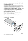
16.Push in on the connector cover to lock the cable into place. See
letter "D" in the figure.
Figure 6. Installing the Floppy Drive into the Chassis
17.Install the chassis cover.
18.(Optional) Install the front bezel.
19.Plug all peripheral devices and the AC power cable back into the
server.
TP013
10
B
C
D
A