


13
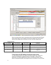
Logic Analyzer Signal Threshold Voltage Settings
Threshold voltage settings are set at SSTL-2 levels (1.25 V) for all pods in the format
specification of the analyzer. The user may have to adjust this setting for optimal
performance for their specific target. Eye Finder and/or EyeScan may have to be run to
find out if adjusting the threshold levels will optimize the data valid windows.
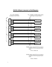
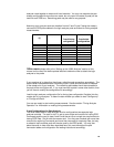
Connecting the Probe to the Logic Analyzer
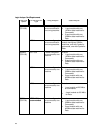
The FS2331 requires two or three logic analyzer cards depending on the DIMM bus
speed, whether state or timing measurements are being used, and the type of logic
analyzer card being used. For timing measurements only two cards (configured as a
single logic analysis module using one analyzer “machine”) are necessary.
Whether using a 2 card or a 3 card configuration, the cards must all be the same model.
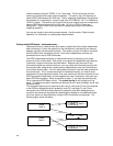
Because the DDR bus clocks commands on one clock and strobes data on a separate
set of strobes, state analysis requires that two separate analyzer “machines” be used,
one for Commands and one for Data. For 200Mhz operation 16750/1/2 (200/400Mhz)
cards provide sufficient speed in their normal mode to capture Data and Commands, so
a two card module configured into one machine for Commands and one for Data is
sufficient. When running at higher speeds, the analyzer capturing Data bursts may need
to be configured to run in its high speed (Turbo) mode, which requires it to be in a
module of its own. A third card configured as a separate module is then needed to
capture and trigger on DDR Commands. Six pods of the data module are used for data
capture (two are reserved for time tags). However, only two pods in the module used to
capture DDR Commands are used for Command capture. The other two may be used
for any other purpose (such as to probe chip select signals of a separate DDR memory
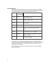
bank). If 16760 cards are being used for both Command and Data analyzers, then 5
cards are required. One card for commands, 4 cards for data. The reason 4 cards are
required for data, is because the cards must be run in 400 Mb/s mode with time tags
turned on for time correlation with the Command machine; with time tags turned on 1
pod per machine cannot be used. With 4 cards connected together as one machine
with time tags on at 400 Mb/s or greater there are 7 pods out of 8 available to use.
Without the 4
th
card only 5 pods would be available, when 6 are needed. A summary of
this information appears on the following table.
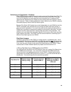
Triggering on a combination of commands and data is accomplished by using the
Intermodule Bus, which sends an "Arm" signal between all analyzer modules. You can
also use the "Flag" bits to communicate between the DDR Command and DDR Data
triggering systems.
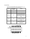
Connecting Power to the FS2331 Probe
After connecting the probe to the logic analyzer cables, insert it into the target system.
After the probe is in the target system and connected to the logic analyzer, connect the
external power supply provided with the FS2331 to the probe. Do this step last and only
use the power supply provided with the FS2331.