


23
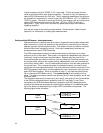
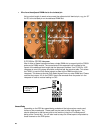
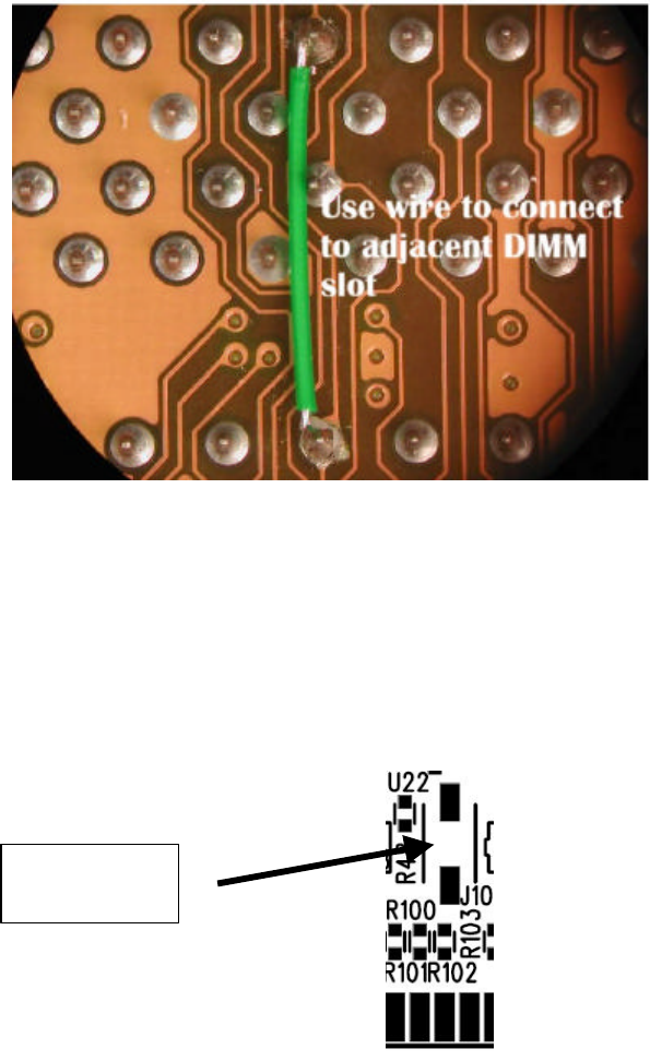
§ Wire from the adjacent DIMM slot to the isolated pin
Using a short length of rework wire connect the adjacent slot’s identical pin, e.g. pin 157
for S0, to the isolated pin on the dedicated DIMM slot.
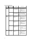
3) FS1024 or FS1025 Interposer
Use of either of these interposers allows a single DIMM slot to support both the FS2331
probe and a DIMM module. The convenience of this approach can be offset by the
impact of the additional etch length that the interposer provides. If an FS1024 or 1025
interposer is used, J5 jumpers should be configured per the previous table. This allows
the FS2331 to use the Chip Select signals as seen by the DIMM module in the
interposer. This does not provide Chip Select signals from any other DIMM slot. Please
note that the jumper J10 on the FS2331 has to be removed when the probe is in the
interposer in order to reduce loading on CK0.
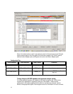
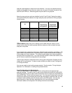
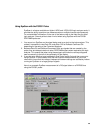
Unused Pods
Depending on the DDR bus speed being probed and the logic analyzer cards used,
there may be unused pods. These pods may be used to trace other signals. You
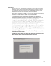
should remember to add the two pods to the machine (using the “Pod Assignment”
dialog of the Format tab). You will also need to setup the format spec to map labels to
these channels on the DDR probe.
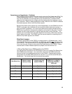
Factory config is
J10 jumper
installed.