


26
Timing Analysis Operation
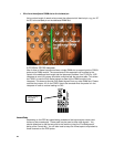
Loading the Inverse Assembler and Decoding DDR Commands
No Inverse Assembler is used for timing analysis. However, symbols are pre-defined for
the DDR Command bus. These decode the RAS, CAS, and WE lines to display the
DDR Command as “Read”, “Write”, “Precharge”, etc., so you don’t have to refer to the
DDR device data sheet to see what command is being executed. Symbols have also
been pre-defined for the Read/Write status generated by the probe.
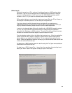
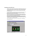
Taking a Trace, Triggering, and Seeing Measurement Results
Timing analysis is the simplest setup, and there are no special factors involved in
analyzer trigger setup, initiating a trace, and viewing results. For the Command bus you
can use the pre-defined symbols to specify mnemonically the command you wish to
trigger on. These are set up by default and are accessible in the trigger tab. The default
waveform display also shows DDR Commands mnemonically.
You may setup a trigger, initiate a measurement, and view results in the usual ways via
the trigger tab, pressing the run button, and opening the desired display window.
State Analysis Operation
The FS2331 DDR Probe supports the simultaneous 200/266/333Mhz DDR state and
2GHz timing measurement capability of the Agilent Logic Analyzers as well as capture
of both Read and Write bursts in a single trace.
The optional calibration procedure documented at the end of this document applies to
state measurements only. You may use the 2GHz TimingZoom feature at any time
during state or timing mode measurements.
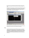
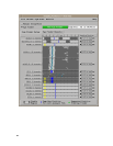
Minimizing intermodule skew
The 16700 will automatically time correlate activity on the Command and Data busses.
The accuracy of the correlation is typically several nanoseconds, but can be larger.
Since even a few nanoseconds is an appreciable fraction of a DDR cycle the DDR
Probe provides a mechanism to reduce the skew to approximately one nanosecond
using the Intermodule Skew adjustment dialog in the 16700 Intermodule setup window.
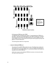
To minimize the skew between the logic analyzer channels tracing the Command and
Data busses a common signal (Buffered Command Clock) is probed by both analyzers.
This signal will have identical timing (within 1ns) as measured by TimingZoom when
the skew between the Command and Data analyzers is minimized. A detailed
procedure to minimize intermodule skew is:
1. Set up the analyzer for state analysis measurements using the procedures
described earlier in this User Manual.
2. Make sure that the TimingZoom feature is enabled for both the Command and
Data analyzers. This is the default when loading a config shipped with the probe.