


45
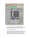
Step 4 – Adjust the delay line value to maximize R/W overlap
You can use the following formula to calculate the proper value for the read delay line
that will maximize overlap between read and write data valid windows:
New U18 Delay Line Value = Current U18 Delay Line Value + (Avg. Read Position –
Avg. Write Position)
For this example the formula yields:
1400ps = 1200ps + (-2250ps – (-2450ps))
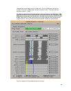
Note that the negative sample position values as indicated in the Eye Finder display are
used in the equation above.
At this point you should not replace the delay line in the “U18” position with the 1700ps
value. Keep in mind the +/-50ps tolerance of the delay lines when adjusting them since
that can cause the actual delay change to be +/-100ps different from the desired
adjustment.
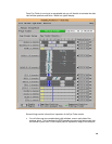
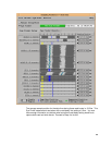
Step 5 – Set the final analyzer sample position
Once the delay line value has been adjusted you are ready to run Eye Finder to set the
final sample position for the logic analyzer to use when capturing both read and write
bursts (SW 6 OFF). To perform this final step you should set the probe configuration
switches to clock both read and write bursts to the analyzer, start your stimulus (that
contains frequent read and write bursts), and run Eye Finder.
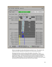
After the EyeFinder process is complete. Inspect the DataClock and all Data windows.
Insure that the sampling position (blue line) is set to the middle of the light gray window
(eye). If they are not they can be moved independently to place them in the middle of
each eye.
The following is a typical resultant display: