


41
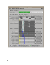
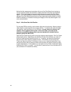
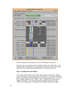
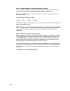
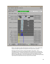
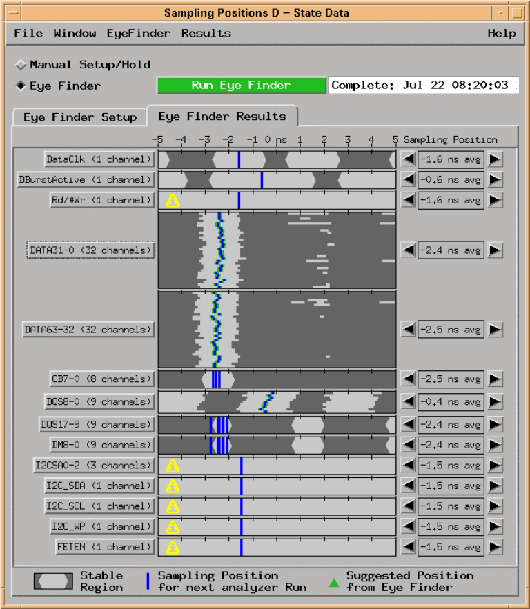
After these adjustments you should see an Eye Finder display like the above:
At this point you should make a note of the sampling position for the data lines. In the
diagram above it is indicated as -2.45ns average for all data lines. This number will be
used later when choosing the proper adjustment for the read burst delay line.
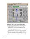
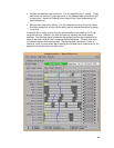
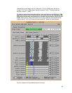
Step 3 – Read Burst Data Valid Position
For this step DDR bus activity must include a high frequency of read bursts. Memory
tests or video clips are usually a good source of such activity. The read burst data valid
position (not duration) is set by the delay line on the probe marked as “U18”. It is a 3 pin
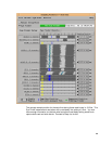
SIP. The factory setting for this is 1200ps +- 50ps. This setting should work well for
333Mhz DDR busses. If you are running your bus at 200Mhz you may find that a
1700ps value is more optimal. (Each delay line provided is marked with two digits