


28
Command and Data analyzers. It can take up to 100ns for the intermodule arm signal to
make it from the Command analyzer to the Data analyzer. For this reason it is not
possible to guarantee a trigger on a burst at a given address which also has a given
data pattern. In general the trigger from the Command/Address analyzer will not
be seen by the Data analyzer until the next burst (or an even later one if bursts are
less than 100ns apart) occurs.
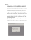
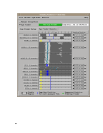
To set up a trigger, open the trigger tab of the setup window of the Command and Data
analyzers, and make adjustments to the default trigger as desired for your
measurement.
If the Data analyzer is running in Turbo mode its triggering capabilities will be more
limited than the Command analyzer. Also, since the data labels are reordered, range
pattern detection will not be available. You can still use store qualification of data within
bursts. You can also use flag bits that may be controlled by the command analyzer. If
you run into resource limitations when trying to look for a pattern on all data bits, you
can usually resolve it by setting a pattern on only 8 or 16 bits in each label, and leaving
the rest as “X” (don’t care).
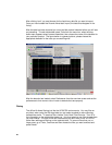
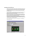
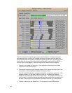
To make a measurement just press the “group run” button and wait for the measurement
to complete. Several display windows have been pre-configured to view measurement
results with the DDR inverse assembler pre-loaded. The workspace window is a good
way to identify each display window and determine which kind of data it displays.
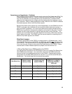
Tracing the Serial Presence Detect Signals
The FS2331 probe can be used along with the Agilent Serial Analysis Tool to decode
the Serial Presence Detect lines and view the SPD programming as bytes rather than as
serial bits. This is best done by setting the Data module in timing mode and using a
slow sample rate about 4x the SPD clock rate.