


19
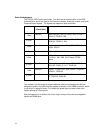
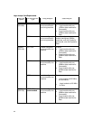
Load the system config file “DR230_2” for 3 card state. This file will cause all three
cards to be configured for state analysis operation. The card in slot C will be setup to
capture DDR Commands at the CK0 rate. The full triggering capabilities of the analyzer
are available if it is operating in “normal” mode (limit of 167Mhz for 16717 or 200Mhz for
16750/1/2 cards). The cards in slot A and B (slot A is the master card) are configured to
capture DDR Data transfers at 2x the CK0 rate. 1671X or 16750/1/2 cards are
configured in “Turbo” mode which provides full speed state analysis with reduced
triggering capability.
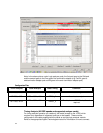
You are now ready to start making measurements. See the section “State Analysis
Operation” for information on making state measurements.
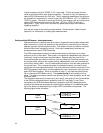
Probing multiple DDR busses – Interleaved memory
Interleaved memory is defined here as a memory system that has multiple independent
banks of memory in which the selection of the active bank is controlled by the memory
address (typically the least significant bits). This allows one bank to initiate a new burst
while the other bank is executing a burst. Each bank independently receives and
processes its own set of DDR Commands.
The DDR probe supports analysis of interleaved memory by allowing you to plug a
probe into a slot on each bank. Each probe is connected to independent logic analyzer
“machines” using the instructions provided above. Because only two pods on the
Command analyzer are used for each bus, you may share the Command analyzer with
the second probe, using its two unused pods to independently trace the Command bus
on the other memory bank. You still need additional cards to trace the data transfers for
the second bank. Thus, to trace two banks of interleaved memory you need 5 cards
configured into three separate modules; One card module split into two machines for the
DDR Commands of each bank, and two separate two card modules for tracing the two
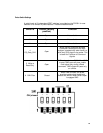
banks DDR Data transfers. Refer to the table on page 17, and load the system config
file for interleaved DDR Banks into all. The system config file will configure all five
cards. The data burst capture modules are assumed to be in slots A(master) and B, and
D(master) and E.
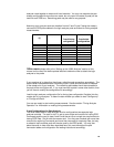
The command capture card is assumed to be in slot C, with pods C3 and C4 connected
to the DDR bus whose data bus is probed by slots D/E, and pods C1 and C2 are
connected to the DDR bus whose data bus is probed by slots A/B. Measurement on
more than two banks are supported by replicating this strategy for the additional banks.
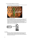
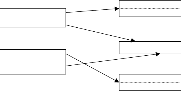
Up to four banks can be analyzed by a single 16700 mainframe and expander. The
following figure shows this setup:
Data
Data
Command
Command
DIMM
Bank 0
DIMM
Bank 1
16700 Slot A
16700 Slot B
16700 Slot D
16700 Slot E
C1/2 C3/4