


37
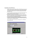
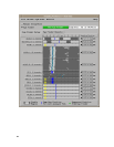
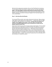
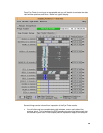
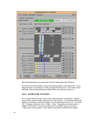
Notice that this measurement was taken with one of the Chip Select lines hooked up.
You can see that its data valid window is smaller than that of the other command bus
signals. This is due largely to the use of soldered wires to connect the Chip Select
signal. Eye Finder provides a convenient way to make sure that the wires you use to
connect to the Chip Select test points are not too long to get a valid indication of which
DIMM is selected (or to make sure that signal integrity for the Chip Select signal is not
overly compromised).
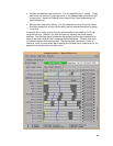
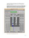
Step 2 – Write Burst Data Valid Position
For this step DDR bus activity must include a high rate of write bursts. Memory tests or
video clips are usually a good source of such activity. To measure the write burst data
valid position, start the stimulus on the DDR bus. In most cases the stimulus will
contain a mix of read and write cycles. If this is the case, you must set the
switches on the DDR probe to select only write bursts to be clocked into the
analyzer (SW-6 ON, SW-5 OFF).
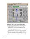
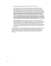
Open the Eye Finder control panel on the logic analyzer capturing data. Run Eye Finder
and note the results. Depending on the density of bursts in the stimulus you may find
that Eye Finder could take quite a while to run. In general, the denser the bursts the
less time Eye Finder needs to complete its work. If the density is too low then Eye
Finder may take as much as 30 minutes or more to run, or may terminate within a few
seconds and report that not enough clocks occurred within a 5 second interval to make
a good measurement. If this happens you can open the “Eye Finder->Advanced” dialog
and select the “Short” run option. You can also try new stimulus or turn the cache off on
your processor to increase burst density.