


Data Ports
Parallel Data Port
162
14178L-001 Rev. A T408M/T408M-R User Guide 1/11/07
Parallel Data Port
The parallel data interface supports IEEE 1284 bidirectional parallel communications in nibble
mode. The parallel interface provides a means of communication that typically is faster than
the serial interface methods. In this method, the bits of data that make up a character are sent
all at one time over several wires in the cable, one bit per wire.
When communicating via the parallel port, the values selected on the printer must be the same
as those used by the host equipment connected to the printer. Port selection for status
information is determined by the channel sending the request. The parallel port can be set for
bidirectional or unidirectional communication. The default setting is bidirectional.
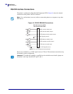
Parallel Cabling Requirements
See IEEE 1284 Bidirectional Parallel on page 21 for basic cabling information.
A standard 36-pin parallel connector is available on the back of the printer for connection to
the data source. An IEEE-1284 compatible bidirectional parallel data cable is required when
this communication method is used. The required cable must have a standard 36-pin parallel
connector on one end that is plugged into the mating connector located at the rear of the
printer. The other end of the cable connects to the printer connector at the host computer. Port
selection for status information is determined each time the printer is turned on.
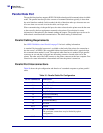
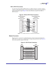
Parallel Port Interconnections
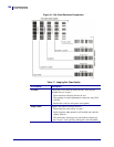
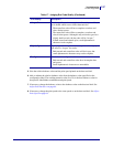
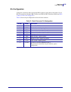
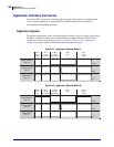
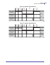
Table 18 shows the pin configuration and function of a standard computer-to-printer parallel
cable.
Table 18 • Parallel Cable Pin Configuration
36-Pin Connectors
Description
1 nStrobe/HostClk
2–9 Data Bits 1–8
10 nACK/PtrClk
11 Busy/PtrBusy
12 PError/ACKDataReq
13 Select/Xflag
14 nAutoFd/HostBusy
15 Not used
16, 17 Ground
18 +5 V at 750 mA
The maximum current draw may be limited by option
configuration.
19–30 Ground