


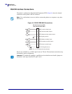
Data Ports
Applicator Interface Connector
170
14178L-001 Rev. A T408M/T408M-R User Guide 1/11/07
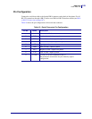
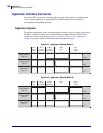
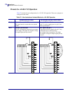
Applicator Interface Connector Pin Configuration
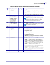
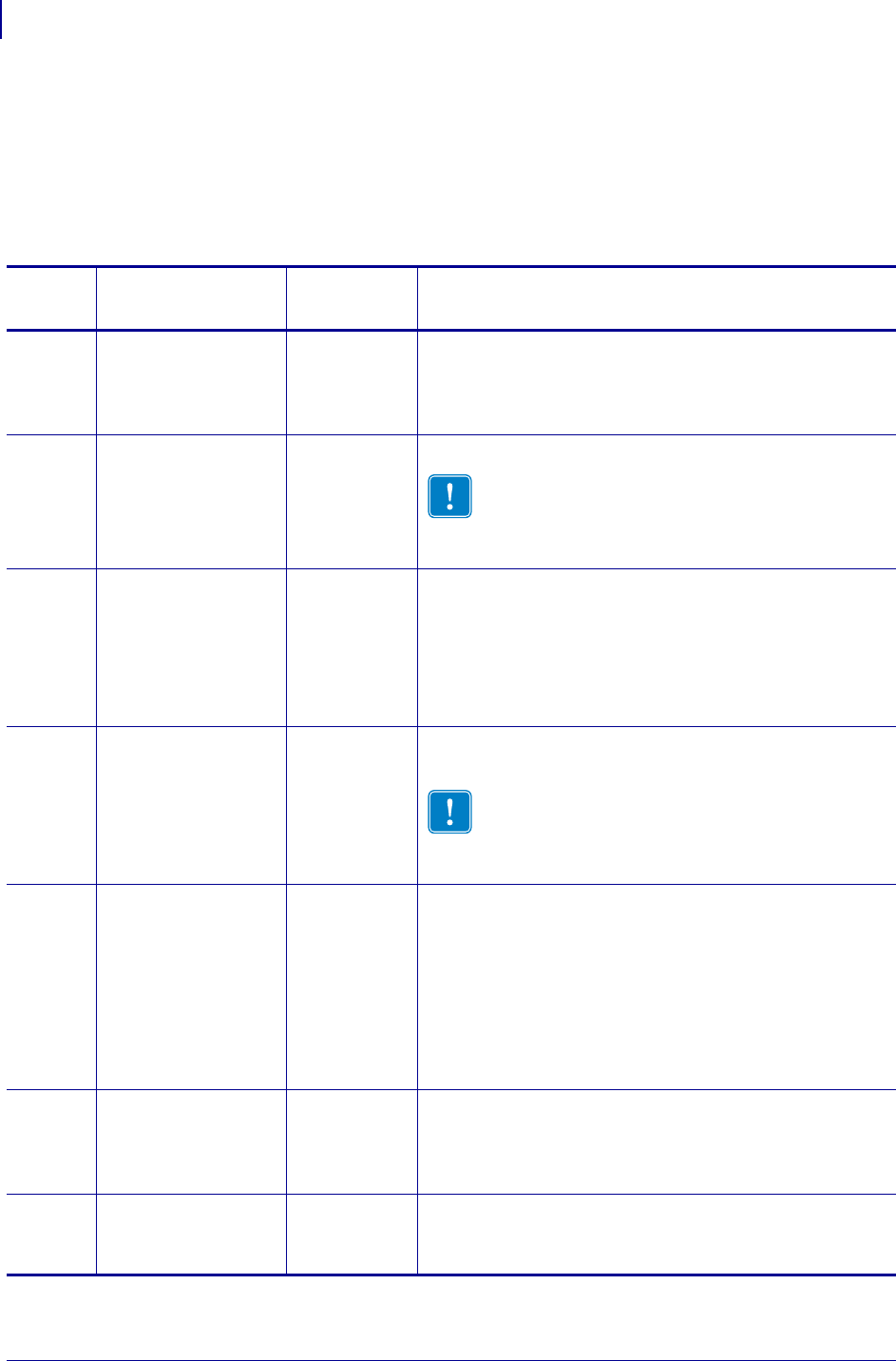
The Applicator Interface Assembly is available in two versions: a +5 V I/O and a
+24–28 V I/O. Table 20 lists the pin configurations and functions of the applicator interface
connector for both +5 V and +24–28 V operation.
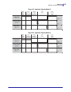
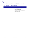
Table 20 • Applicator Interface Connector Pin Configuration
Pin
No.
Signal Name Signal Type Description
1 I/O SIGNAL
GROUND
(+5V Return)
I/O Signal
Ground
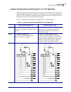
Using jumper J5, this pin can be configured as isolated or
non-isolated from the printer signal ground. See Jumper
Configurations and Pinouts for +5 V I/O Operation
on page 173 for more information.
1 I/O SIGNAL
GROUND
(+24-28V Return)
I/O Signal
Ground
No jumpers to configure.
Important • Customer must provide this external
ground (can come from pin 8). See Pinouts for
+24-28 V I/O Operation on page 174 for more
information.
2+5V I/O
(Fused at 1 A)
Caution • Replace
the fuse only with
one of the same
type and rating.
Power Using jumper J4, this pin can be configured as isolated or
non-isolated from the Applicator Interface Circuit +5 V
Supply. See Jumper Configurations and Pinouts for +5 V
I/O Operation on page 173 for more information.
2 +24-28V I/O Power No jumpers to configure. This +24-28V power source
also supplies voltage for output signal pull-up resistors.
Important • Customer must provide this external
power (can come from pin 7). See Pinouts for
+24-28 V I/O Operation on page 174 for more
information.
3 START PRINT Input • Pulse Mode—The label printing process begins on the
HIGH to LOW transition of this signal if a format is
ready. Deassert this signal HIGH to inhibit printing of
a new label.
• Level Mode—Assert LOW to enable the printer to
print if a label format is ready. When deasserted HIGH,
the printer completes the label that is printing then
stops and waits for this input to be reasserted LOW.
4 FEED Input When the printer is idle or has been paused, assert this
input LOW to trigger repeated feeding of blank labels.
Deassert HIGH to stop feeding blank labels and register
to the top of the next label.
5 PAUSE Input To toggle the current Pause state, this input must be
asserted LOW for 200 milliseconds, or until the
SERVICE REQUIRED output (pin 10) changes state.