


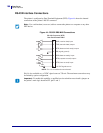
Data Ports
Applicator Interface Connector
174
14178L-001 Rev. A T408M/T408M-R User Guide 1/11/07
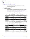
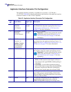
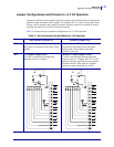
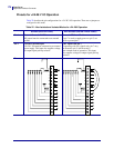
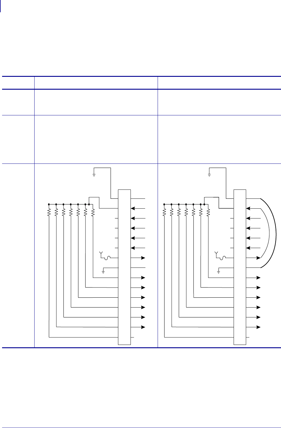
Pinouts for +24-28 V I/O Operation
Table 22 describes the pin configurations for +24–28 V I/O operation. There are no jumpers to
configure for this mode.
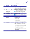
Table 22 • Non-Isolated and Isolated Modes for +24–28V Operation
Isolated (External Power) Non-Isolated (Internal Printer Power)
Pin 1 External Ground +24-28V
I/O ground must be connected to an external
ground.
Ground +28V from Pin 8
If pin 7 is used to supply power to pin 2, use
pin 8 to ground pin 1.
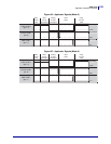
Pin 2 +24-28V External Input
+24-28 V I/O must be connected to an external
power supply. This input also supplies voltage
for output signal pull-up resistors.
+28V Input from Pin 7
If operating with 28V signals only, pin 7 may
be shorted to pin 2, which creates a
non-isolated mode of operation. This input
also supplies voltage for output signal pull-up
resistors.
Pinouts
2
3
4
5
6
7
8
9
1
10
11
12
13
14
15
+24-28V
+28V
+28V
500 mA
500 mA
+24-28V
2
3
4
5
6
7
8
9
1
10
11
12
13
14
15
+28V
+28V
+28V
+28V
500 mA
500 mA