


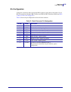
Data Ports
Serial Data Port
166
14178L-001 Rev. A T408M/T408M-R User Guide 1/11/07
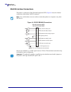
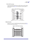
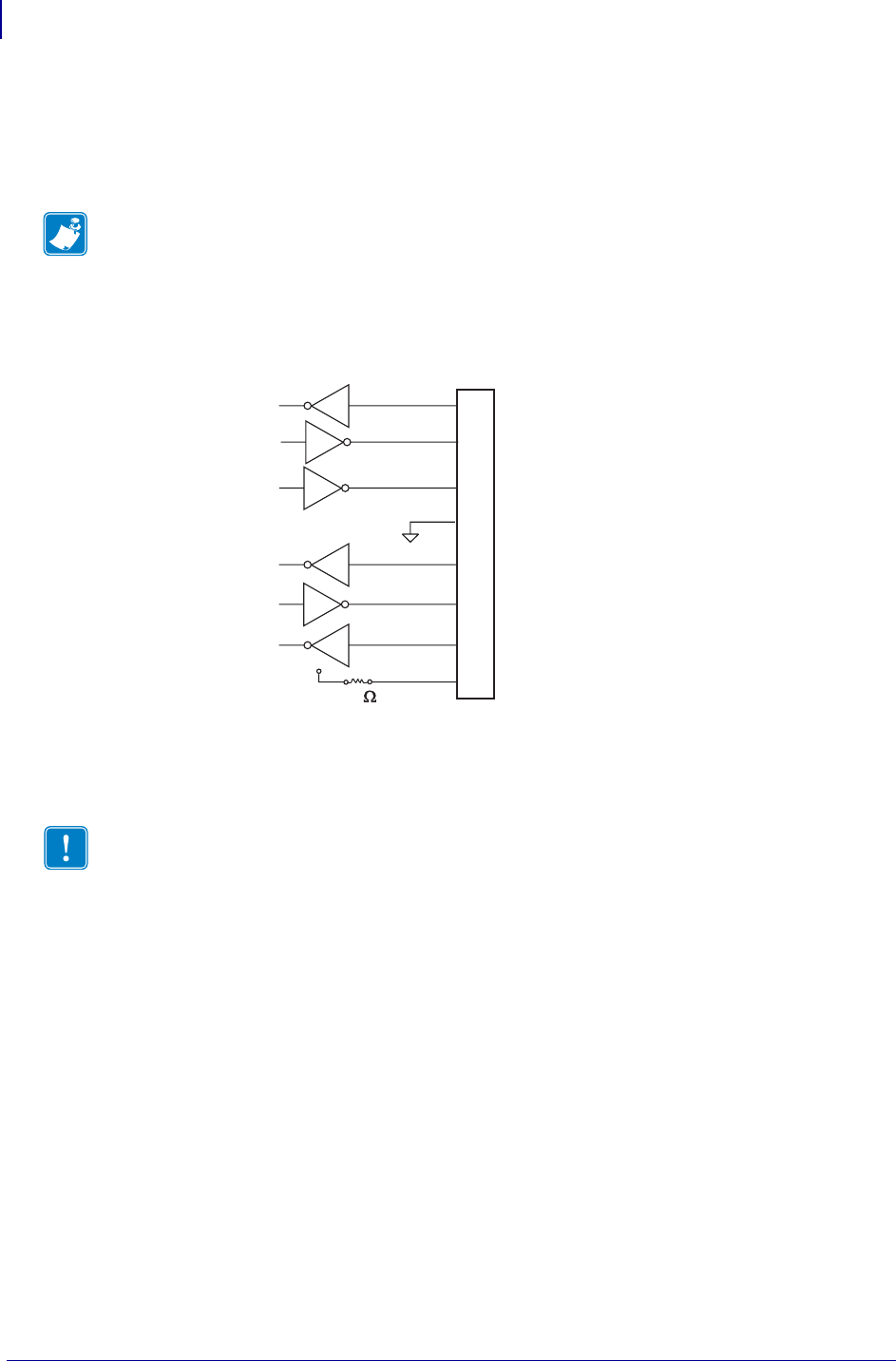
RS-232 Interface Connections
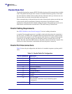
The printer is configured as Data Terminal Equipment (DTE). Figure 44 shows the internal
connections of the printer’s RS-232 connector.
Figure 44 • RS-232 DB9 MLB Connections
Pin 9 is also available as a +5 VDC signal source at 750 mA. The maximum current draw may
be limited by option configuration.
Note • Use a null modem (crossover) cable to connect the printer to a computer or any other
DTE device.
Important • To enable this capability, a qualified service technician must install a jumper on
the printer’s main logic board on JP1, pins 2 and 3.
NOTE: Pin 1 is unused and unterminated.
RS-232 Connector (DTE)
Rear Panel Female DB-9
RXD (receive data) input
TXD (transmit data) output
DTR (data terminal ready) output
SG (signal ground)
DSR (data set ready) input
RTS (request to send) output
CTS (clear to send) input
+5 VDC signal source
2
3
4
5
6
7
8
9
R1
+5 VDC
1K