


165
Data Ports
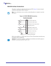
Serial Data Port
1/11/07 T408M/T408M-R User Guide 14178L-001 Rev. A
Pin Configuration
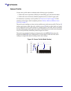
Connect the serial data cable to the female DB-9 connector on the back of the printer. For all
RS-232 connections through a DB-25 cable, use a DB-9 to DB-25 interface module (see DB-9
to DB-25 Connections on page 167).
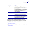
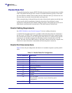
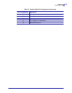
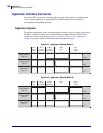
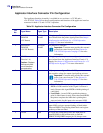
Table 19 shows the pin configuration of the serial data connector.
Table 19 • Serial Connector Pin Configuration
Pin No. Name
Description
1 +5 VDC Connected to Pin 9
2 RXD Receive data—data input to printer
3 TXD Transmit data—data output from printer
4 DTR Data terminal ready—output from printer
5 SG Signal ground
6 DSR Data set ready—input to printer
7 RTS Request to send—output from printer
8 CTS Clear to send—input to printer
9 +5 VDC +5 VDC at 750 mA (connected to Pin 1)
The maximum current draw may be limited by option
configuration.