


13
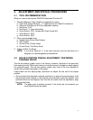
TURN
CLOCKWISE
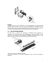
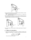
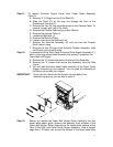
• Using a flat-head screwdriver, turn the adjustment screw clockwise or counter-
clockwise to move the die set position cradle.
NOTE: Seven full turns of the adjustment screw result in a ¼” change in the
punched hole position.
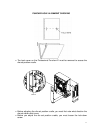
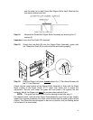
• Before tightening the lock-down screw, tilt or bias the assembly towards the
bottom of the machine and tighten the lock-down screw. This will ensure positive
engagement between the locking lever and the die set.
TILT TO BOTTOM
OF M/C
SCREW
TIGHTEN
• Run a test sample of punched paper and recheck paper alignment. Re-adjust if
necessary.
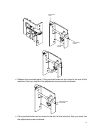
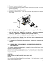
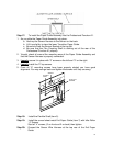
4.3 REMOVAL OF PUNCH MODULE
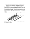
1. Examine the Drive Belts. Note the consistency in tightness of the belts. They
should all have approximately ¼” of deflection; remove the four drive belts items
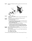
1, 2, 3, 4.
Disconnect the Sensor Wire Connection