


24
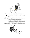
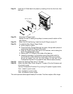
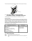
Step 10: To remove the Rear, Drive Side, and Paper Guide Aligner Assembly.
This is the large Sheet Metal Assembly within the Professional Puncher-
A1 that actually contains the Green Belt Aligner itself.
IMPORTANT: Walk the Belt off of the Aligner Pulley at the rear.
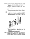
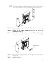
A. Remove the “2” screws that hold the Block to the Frame. Now – the
Coupler is loose and the Rear Panel will come out.
B. Remove the “6” Screws that secure the face of this Assembly.
C. Remove the “2” Screws that secure this Assembly from the top.
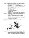
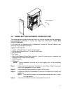
D.
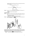
Pull and walk the entire sheet metal assembly of the Paper Guide Aligner
up and outward. You can grab the Assembly at the Roller cut out with your
fingers.
NOTE: The Helical coupling is very delicate, be gentle.
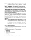
NOTE: In order to access these screws, you must first remove the Die Set
Storage Shelf and the Cable Shield attached to the Die Storage Shelf
at the paper entrance side. Moving the Die Storage Shelf aside will
enable better access to the “2” screws with a short (7” or less) Phillips
Screw Driver.
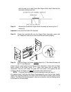
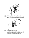
ALIGNER DRIVE
BELT ASSY
E. Bend in the Tab of the frame near the middle, front area to allow
enough clearance to work the sheet metal Paper Guide Aligner
Assembly out.
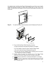
IMPORTANT: As you do this, disconnect the Sensor harness behind
the Assembly as soon as you are able to reach it.
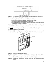
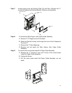
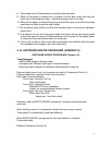
Step 11: Before you remove the Green Belt Aligner Roller Assembly from the
sheet metal paper guide, observe the perfectly flush surfaces of the
Green Belt Aligner Roller Assembly to the sheet metal surface of the
Rear, Drive Side, Paper Guide Aligner Assembly. Hold a straight edge
like a 12”metal ruler across the surface of the sheet metal face and the