


27
E. Once all “8” mounting screws have been properly started you have
good alignment. You may now go back and tighten the screws until
they are snug. Do not over tighten the “2” screws on top!
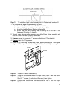
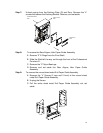
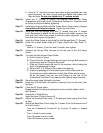
Step 16: Install the “2” Screws to secure the Bearing Block for the Pulley
arrangement at the rear of the Professional Puncher-A1. Press the block
to the top of the punch before tightening
Step 17: Install the Pulley and Belt onto the Pulley Block. Once properly aligned,
check Belt and Pulley movement
. Tighten the Set Screw.
Step 18: Install the Die Set Storage Rack with “3” screws front and “3” screws
back. Remember to attach the Ground Strap at the middle screw on the
rear (belt side). Start each screw to achieve proper alignment, then go
back over each screw and tighten it.
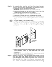
Step 19: Install the Cable Guard on top of the Die Set Storage Rack (“2” Screws).
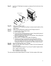
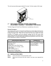
Step 20: Install the curved sheet metal Exit Paper Guide with Idler Roller “4”
Screws.
Start all “4” screws, (2 on front and 2 on back) then tighten.
Step 21: Connect the Sensor Wire Harness at the top rear of the Exit Paper
Guide.
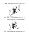
Step 22: To install the Idler Aligner Paper Guide.
A. Hold it loosely in place.
B. Press the Nylon Flange Bearings into place, through both pieces of
sheet metal, with the Flange to the inside.
C. Slide the Shaft through the front of the machine, while holding the
Nylon Flange Bearing in place.
D. Secure with “2” E-Rings on the inside of the bearing.
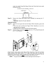
E. Inspect by pressing in on the bottom area of the sheet metal for:
#1 should see a slight deflection of each Idler Roller as you press,
#2 as you press, you can turn the Pulley’s at the rear of the
Professional Puncher-A1 and see the Idler Rollers rotate smoothly.
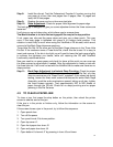
Step 23: Bend the small metal tab back into place.
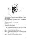
Step 24: Install the J2 Shaft back into place by inserting it first into the front, then
the back.
Step 25: Close the J2 Flipper Latch.
Repeat the test of rotating the pulleys to ensure smooth rotation of the
Idler Rollers.
Step 26: Attach the J2 Shaft Spring
Install the front E-Ring to secure J2.
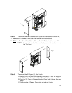
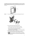
Step 27: Attach the Docking Plate using “4” Screws and install spring from Plate
to Door.
Step 28: Attach the Back Rear Cover using the 7 screws (2 for the Entrance and 5
for the Exit side).
Test the Professional Puncher-A1 by running 10 copies in bypass
mode,
Then 1 sheet in punch mode,
Then 10 sheets in punch mode,
Then 100 sheets in punch model