


35
SERIAL EEPROM CONTROL:
1 Input 3 Outputs Counts number of punches for die set full, Saves value
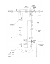
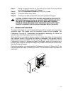
For the Stream Punch to operate, all optical sensors must be clear. Any blocked
sensor or open door will prevent operation. The machine may operate in bypass
mode with or without a chip tray or die set. Both of these must be present to punch.
Stepper #1 Control:
If punch is not enabled, the Professional Puncher-A1 will run in bypass mode (no
punching). Either the printer or the first sheet entering the machine will turn on both
stepper motors. The time is measured for the leading edge of the first sheet to pass
sensor 8. Knowing the distance between sensors and the time it takes for the sheet
to pass both sensors, we can determine the speed of the paper. The time is
compared to a list and Stepper 1 and stepper 2 are adjusted to closely match the
incoming speed.
If the punch is enabled, the backstop is raised, the brake is engaged, and both the
transport and punch motors are started. Also, the divert solenoid is activated to
direct the sheets into the punch path. As above, the input speed is measured, this
time using Sensor 1 and 2. Stepper 1 is adjusted to meet the measured input speed;
Stepper 2 is accelerated to the speed of the transport motor. Sensor 2 now delays
for a time period based on the input speed to ensure that the sheet has cleared the
printer exit roller. After this delay, stepper 1 accelerates the sheet to match the
transport speed. 19 msec after the sheet’s trailing edge passes sensor 2, Stepper 1
is decelerated to match the previously measured input speed.
Punch Control:
The punch cycle begins 40 msec after the leading edge of the sheet reaches Sensor
3. The brake is released, and the clutch is engaged. Sensor 9 now looks for the
leading edge of its flag, and when seen, the clutch is disengaged, and the backstop
is lowered. When the trailing edge of the flag is seen, the brake is engaged. When
Sensor 3 sees the trailing edge of the sheet, the backstop is raised.
Stepper #2 Control:
72msec after the leading edge of the sheet passes Sensor 6, Stepper 2 is
decelerated to match the measured input speed from the printer. This delay ensures
that the sheet exits from the transport rollers. When the trailing edge of the sheet
passes Sensor 6, Stepper 2 is accelerated to match the speed of the transport
motor.
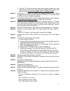
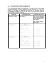
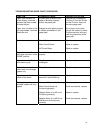
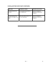
GENERAL TROUBLESHOOTING:
One of the first rules of troubleshooting is to first understand the normal operating
sequence of the machine. Then carefully listen to the key operator’s description of
the problem or complaint. Follow this by your own visual observation. The cause of
the problem can be determined by noting at which point in the operating cycle the
problem occurred. To pinpoint the problem to a defective electrical component or
mechanical part, use the Troubleshooting Guide and the Electrical Schematic
Diagram.
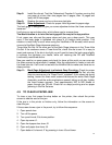
During any service call, it is a good practice to check the cable connections for fit
and alignment.