


21
AFTER ASSEMBLY
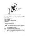
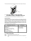
4.6 GREEN BELT REPLACEMENT, PAPER EXIT SIDE
The following step-by-step directions inform you how to remove and then assembly
the components necessary to access the Paper Exit Side Aligner Green Belt,
P/N FC3-3633-0000
It will help you to reference your Professional Puncher-A1 Service Manual part
drawings as you follow this process.
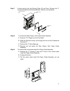
Special Tools Required:
• Twelve inch metal ruler or similar straight edge.
• Phillips Head Screw Driver 7” or less in total length.
• Alan wrenches.
• Nut Driver
• Rare Earth Magnet Snake Neck (optional – good for retrieving any hardware that
happens to fall in hard to reach spots)
• Snap Ring pliers
• E-Ring tool
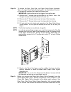
NOTE: During assembly, be sure not to over tighten any of the mounting
screws.
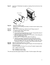
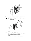
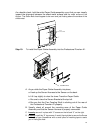
Step 1: Disconnect the Professional Puncher-A1 from Power. Retain the power
cord in your possession for your safety.
Step 2: Disconnect the Communication Cable to the Finisher.
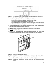
Step 3: Unlatch the CANON Professional Puncher-A1 from both the Finisher and
the Printer.
NOTE: You must first remove the screw that secures the latch in place
(if so equipped).
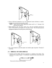
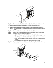
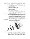
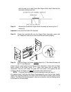
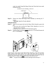
Step 4: Open the front door (A) of the Professional Puncher-A1.