


23
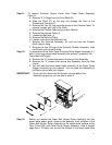
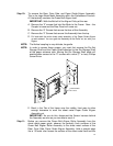
Step 7: Unhook spring from the Docking Plate (D) and Door. Remove the “4”
screws that secure the Docking Bracket. Remove, and set aside.
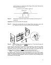
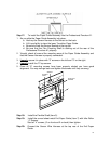
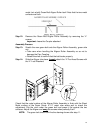
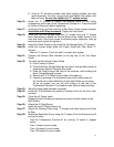
PAPER EXIT
SIDE
FRONT DOOR
SIDE
PAPER ENTERANCE
SIDE
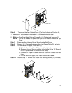
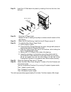
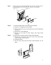
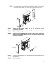
Step 8: To remove the Rear Aligner, Idler Paper Guide Assembly
A. Remove “2” E-Rings from the Pivot Shaft.
B. Slide the Shaft all the way out through the front of the Professional
Puncher-A1.
C. Remove the “2” Nylon Bearings.
D. Remove and set aside the Rear Aligner, Idler Paper Guide
Assembly.
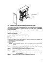
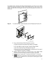
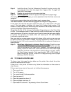
Step 9: To remove the curved sheet metal Exit Paper Guide Assembly
A. Remove the “4” Screws (2 rear and 2 front) of the curved sheet
metal Exit Paper Guide Assembly
B. Unplug the Sensor
C. Pull the entire sheet metal Exit Paper Guide Assembly out, set
aside.