


14
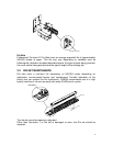
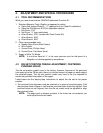
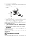
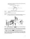
2. Remove 4 screws in front and 2 in back
3. Cut any wire ties that may prevent freedom of movement to slide the Punch
Module (A) outward
4. Remove the Back Gauge Assembly (B).
5. Remove the black Knob (C) at the front (customer side) of the Punch Module
Drive Shaft.
FRONT SIDE
C
A
B
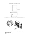
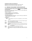
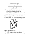
6. Slide the Punch Module unit part way out to reach and unplug the Punch Sensor
Harness (Red, Black, White wires)
7. Slide the entire Punch Assembly (C) out and lay it beside the Professional
Puncher-A1. Take care not to damage wires or Rollers as you do so.
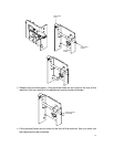
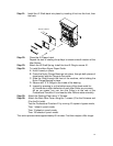
8. Lubricate the Drive Cams sparingly of the punch module using a multi-purpose,
extreme pressure lubricant, preferably formulated with Teflon.
Note: This lubrication is not required during the normal life but is reasonable to do
this of the module every needs service.
9. To replace any component of the punch Module, disassemble components as
required
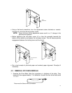
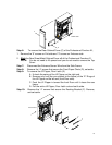
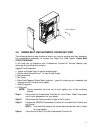
4.4 GREEN BELT REPLACEMENT, ALIGNER PANEL REMOVAL,
EXPLANATION
The following procedure explains how to remove the Entrance Side Aligner Panel
and the Exit Side Aligner Panel.
The basic intent of this procedure is to access and replace the Green Aligner Belts,
but once you know how to follow this procedure you are now able to access other
components as well.
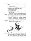
SYMPTOM
Paper will stop moving through the Punch paper path.
CAUSE
One or both of the Green Aligner Belts have broken. If this break occurs, it would
usually occur at the Weld Splice.