


17
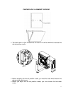
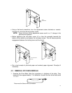
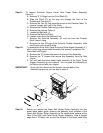
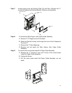
Step 11: To remove Entrance Aligner Panel, Idler Paper Guide Assembly
(item 19)
A. Remove “2” E-Rings from the Pivot Shaft (G).
B. Slide the Shaft (G) all the way out through the front of the
Professional Puncher-A1.
C. Remove the Fan (H) that prevents access to the Flexible Cable. To
remove it simply pull it off of the Shaft.
D. Remove the Flexible Cable using an Alan Wrench.
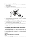
E. Remove the rear top Pulley (I).
F. Loosen the Belt Idler (J).
G. Remove the Belt and Pulley.
H. Loosen screw from the Solenoid Link.
I. Remove the Solenoid Assembly (K) and link from the Diverter
Shaft, leave it hang.
J. Remove the two E-Rings of the Entrance Diverter Assembly, slide
the Diverter out and set it aside.
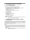
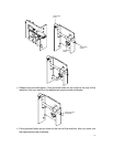
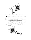
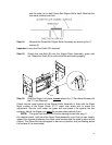
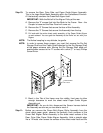
Step 12: To remove the Drive Side, Paper Entrance Guide Aligner Assembly (L),
which is the large sheet metal Assembly that actually, containers the
Green Belt and Aligner.
A. Remove the “6” Screws that secure the face of this Assembly.
E. Remove the “2” screws that secure this Assembly from the Side
Frame.
F. Pull and walk the entire sheet metal assembly of the Paper Guide
Aligner Assembly up and outward. You can grab the Assembly at
the Roller cut out with your fingers.
IMPORTANT: As you do this, disconnect the Sensor harness behind the
Assembly as soon as you are able to reach it.
K
G
H
I
L
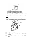
Step 13: Before you remove the Green Belt Aligner Roller Assembly from the
sheet metal paper guide, observe the perfectly flush surfaces of the
Green Belt Aligner Roller Assembly to the sheet metal surface of the
Rear, Drive Side, and Paper Guide Aligner Assembly. Hold a straight
edge like a 12”metal ruler across the surface of the sheet metal face