


26
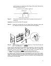
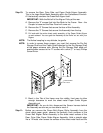
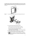
As a double check, hold the entire Paper Guide assembly up so that you can visually
inspect the alignment between the sheet metal surface and
the metal surface of the
Aligner. The Green Belt should appear to be even and just floating above the surface of the
sheet metal.
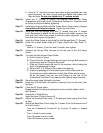
ALIGN
& FIX SCREWS
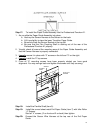
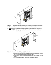
Step 15: To install the Paper Guide Assembly into the Professional Puncher-A1.
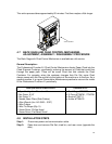
ASSEMBLE BACK
A. As you slide the Paper Guide Assembly into place,
a. Hook up the Sensor Harness to the Sensor on the back.
b. Lift it up slightly to clear the lower Transition Paper Guide.
c. Be sure to clear the Sensor Bracket at the top left.
d. Be sure that the Flex Coupling Shaft is sticking out of the rear of
the Professional Puncher-A1 properly.
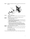
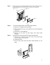
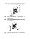
B. Visually check all around the mounting area of the Paper Guide
Assembly and that the Sensor Harness is properly connected.
C. Loosely secure it in place with “3” screws on the left and “3” on the right.
D. Loosely
install the “2” top screws. A useful tip might be to secure the Screw
to the tip of your Screwdriver with a small piece of masking tape to assist
you in finding the hole.