


19
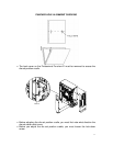
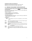
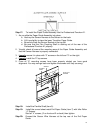
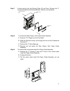
Step 17: To install the Paper Guide Assembly into the Professional Puncher-A1.
1. As you slide the Paper Guide Assembly into place,
a. Hook up the Sensor Harness to the Sensor on the back.
b. Lift it up slightly to clear the lower Transition Paper Guide.
c. Be sure to clear the Sensor Bracket at the top left.
d. Be sure that the Flex Coupling Shaft is sticking out of the rear of the
Professional Puncher-A1 properly.
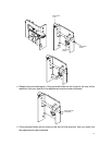
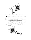
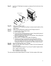
2. Visually check all around the mounting area of the Paper Guide Assembly and
that the Sensor Harness is properly connected.
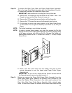
3. Loosely
secure it in place with “3” screws on the left and “3” on the right.
4. Loosely
install the “2” top screws.
5. Once all “8” mounting screws have been properly started you have good
alignment. You may now go back and tighten the screws until they are snug.
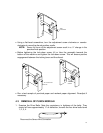
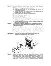
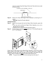
SENSOR
FLEXIBLE
SHAFT
ALIGN & FIX
SCREWS
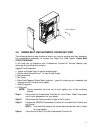
Step 18: Install the Flexible Shaft (item 5).
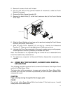
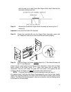
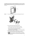
Step 19: Install the curved sheet metal Exit Paper Guide (item 7) with Idler Roller
“4” Screws.
Start all “4” screws, (2 on front and 2 on back) then tighten.
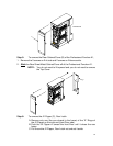
Step 20: Connect the Sensor Wire Harness at the top rear of the Exit Paper
Guide.