


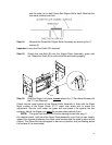

18
and the metal (w/o a belt) Green Belt Aligner Roller itself. Note that the
two metal surfaces are flush.
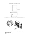
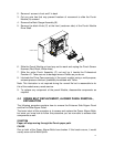
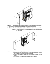
Step 14: Remove the Green Belt Aligner Roller Assembly by removing the “4”
screws (S).
Important: Leave the Flex Shaft (FS) attached.
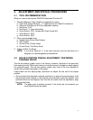
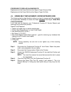
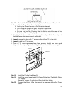
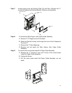
Step 15: Stretch the new Belt (B) onto the Aligner Roller Assembly, green side
out. Rotate the Shaft (S) to confirm that the belt tracks properly.
STRETCH
B
FS
S
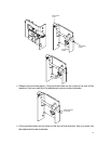
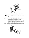
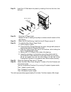
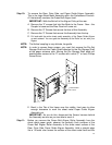
Step 16: Slide the Aligner into place, loosely
attach the “4” Pan Head Screws with
the “4” Lock Washers.
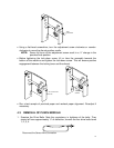
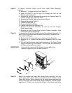
Check that the metal surface of the Aligner Roller Assembly is flush with the Sheet
Metal surface of the Paper Guide. A 12” metal ruler works well to check this
adjustment. Slip the ruler under the green belt and press it flat against the two
surfaces. Adjust the Aligner and snug
the screws when perfectly flush.
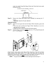
NOTE: The green belt should look like the drawing shown after step 11.
As a double check, hold the entire Paper Guide assembly up so that you can visually
inspect the alignment between the sheet metal surface and the metal surface of the
Aligner. The Green Belt should appear to be even or parallel, and just floating above
the surface of the sheet metal.