


15
PROCEDURE TO REPLACE ALIGNER BELTS
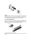
Replacement of the Green Belt from the Aligner, Paper Entrance Side.
Replacement of the Green Belt from the Aligner, Paper Exit Side.
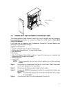
4.5 GREEN BELT REPLACEMENT, PAPER ENTRANCE SIDE
The following step-by-step directions inform you how to remove and then assembly
the components necessary to access the Paper Entrance
Side Aligner Green Belt,
P/N FC3-3633-0000
It will help you to reference your Professional Puncher-A1 Service Manual part
drawings as you follow this process.
Special Tools Required:
• Twelve inch metal ruler or similar straight edge.
• Phillips Head Screw Driver 7” or less in total length.
• Alan wrenches (5/64” & 9/64”).
• Nut Driver (1/4” & 5/16”)
• Rare Earth Magnet Snake Neck (optional – good for retrieving any hardware that
happens to fall in hard to reach spots)
• Snap Ring pliers
• E-Ring tool
NOTE: During assembly, be sure not to over tighten any of the mounting
screws.
Step 1: Disconnect the Professional Puncher-A1 from Power. Retain the power
cord in your possession for your safety.
Step 2: Disconnect the Communication Cable to the Finisher.
Step 3: Unlatch the CANON Professional Puncher-A1 from both the Finisher and
the Printer.
NOTE: You must first remove the screw that secures the latch in place
(if so equipped).
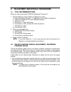
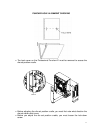
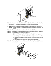
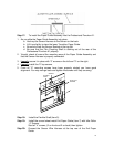
Step 4: Open the Front Door (A) of the Professional Puncher-A1.
Step 5: Remove the Paper Chip Tray (B), empty it and replace it. This is to
prevent difficulty in finding any small parts that you may drop into the
chad