


1-6
Cisco AS5800 Universal Access Server Dial Shelf Card Guide
78-7097-03 0A
Chapter1 Replacing or Installing Dial Shelf Cards
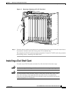
Installing a Dial Shelf Card
Step 1 Attach an ESD-preventive wrist strap between you and an unpainted chassis surface.
Caution To prevent ESD damage, handle cards by ejector levers and carrier edges only, and use an
ESD-preventive wrist strap or other grounding device.
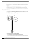
Step 2 Carefully align the card carrier guides with the top and bottom grooves in the dial shelf slot. Avoid
touching the circuitry or any connector pins.
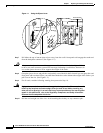
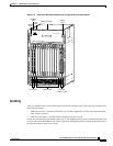
Step 3 Slide the card into the slot until the ejector levers make contact with the chassis frame. (See Figure 1-2.)
Step 4 Seat the card in the backplane by pushing the card firmly until the ejector levers fold in toward the card’s
front panel and the front panel is flush with the chassis frame.
Caution Always use the ejector levers to disengage or seat trunk cards, modem cards, VoIP cards,
or dial shelf controller cards in the backplane. Failure to do so can cause erroneous system
error messages indicating a card failure. However, do not use the ejector levers to lift or
support the weight of the cards.
Step 5 Tighten the panel fasteners using a No. 2 Phillips screwdriver. This secures the backplane connection
and ensures proper EMI shielding.
Caution Always tighten the panel fasteners. These fasteners prevent accidental removal and provide
proper grounding for the system.
Step 6 Repeat Step 2 through Step 5 for any other CT1/CE1 trunk cards that you want to install.
Step 7 Install a blank filler card (DS58-BLANK=) in all empty card slots to keep the chassis dust-free and
maintain proper airflow.
Caution To prevent the overheating of internal components, always install blank filler cards in
empty slots to maintain the proper flow of cooling air across the cards.
This completes the CT1/CE1 trunk card replacement procedure.