


2-12
Cisco AS5800 Universal Access Server Dial Shelf Card Guide
78-7097-03 0A
Chapter 2 Channelized T1 or E1 Trunk Card
CT1 and CE1 Trunk Card Overview
Warning
To avoid electric shock, do not connect safety extra-low voltage (SELV) circuits to
telephone network voltage (TNV) circuits. LAN ports contain SELV circuits and WAN
ports contain TNV circuits. Some LAN and WAN ports both use RJ-45 connectors. To see
translations of the warnings that appear in this publication, refer to the Regulatory
Compliance and Safety Information that accompanied this device.
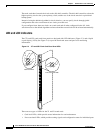
Connecting Trunk Card Cables
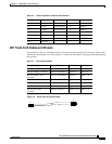
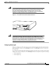
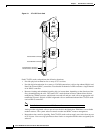
The CT1 and CE1 trunk cards provide 12 RJ-45 receptacles for T1 or E1 lines. To connect T1or E1 lines,
follow these steps:
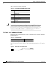
Step 1 Attach the RJ-45 end of the T1 or E1 cable directly to the RJ-45 receptacle on the trunk card. (See
Figure 2-11.)
Step 2 For T1 cabling, attach the network end of your CT1 cables to your external network.
Step 3 For E1 cabling, attach the network end of your CE1 cables to your network termination (NT1) device.
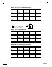
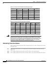
Table 2-13 RJ-45 to RJ-45 TE Cable Pinouts (Straight-through)
RJ-45 Pin Signal Description Direction RJ-45 TE Pin
Shield Ground Shell/Braid — Shield
J1-1 RX Tip Twisted Pair #1 <— J2-1
J1-2 RX Ring Twisted Pair #1 <— J2-2
J1-3 RX Shield Twisted Pair #3 — J2-3
J1-4 TX Tip Twisted Pair #2 —>J2-4
J1-5 TX Ring Twisted Pair #2 —>J2-5
J1-6 TX Shield Twisted Pair #4 — J2-6
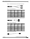
Table 2-14 RJ-45 to RJ-45 NT Cable Pinouts (Crossover)
RJ-45 Pin Signal Description Direction Signal RJ-45 NT Pin
Shield Ground Shell/Braid — Ground Shield
J1-1 RX Tip Twisted Pair #1 <— TX Tip J2-4
J1-2 RX Ring Twisted Pair #1 <— TX Ring J2-5
J1-3 RX Shield Twisted Pair #3 — TX Shield J2-6
J1-4 TX Tip Twisted Pair #2 —>RX Tip J2-1
J1-5 TX Ring Twisted Pair #2 —>RX RingJ2-2
J1-6 TX Shield Twisted Pair #4 — RX Shield J2-3