


Index
2
Cisco AS5800 Universal Access Server Dial Shelf Card Guide
78-7097-03 0A
D
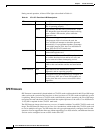
DMM Card LED Descriptions (Table 4-1) 4-5
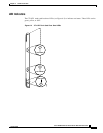
DMM modem card
components
4-1
configuration 4-7
LEDs 4-4
overview 4-1
verifying and troubleshooting 4-6
documentation
CD-ROM
xii
Cisco 7206 router shelf xii
Cisco IOS software xii
conventions used in viii
list of related xii
network management xii
system controller xii
Double-Density Modem Card Components (Figure
4-1)
4-1
Double-Density Modem Card Front Panel LEDs (Figure
4-3)
4-4
E
Electrostatic discharge (ESD) x
F
Front Panel LEDs (Figure 5-2) 5-5
L
LEDs
CT3 trunk card
3-4
DMM modem card 4-4
T1/E1 trunk card 2-4
VoIP card 5-5
M
MICA 4-1
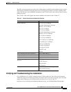
Modem Standards and Supported Features (Table
4-2)
4-6
Modem Standards and Supported Features (Table
6-2)
6-5
N
note, definition viii
O
online insertion and removal (OIR) 1-1
P
ports, monitoring, using bantam jacks 2-5
R
Related and Referenced Documents (Table 1) xiii
Removing or Replacing a Dial Shelf Card (Figure
1-2)
1-5
RJ-45-to-Bare-Wire Interface Cable (Figure 2-5) 2-8
RJ-45-to-Bare-Wire Interface Cable Pinouts (Table
2-6)
2-9
RJ-45-to-BNC Cable Pinouts (Table 2-11) 2-11
RJ-45-to-BNC Interface Cable for 75-Ohm Unbalanced
Connections (Figure 2-8)
2-11
RJ-45-to-DB-15 Cable Pinouts (Table 2-9) 2-10
RJ-45-to-DB-15 Interface Cable (Figure 2-7) 2-10
RJ-45-to-DB-15 Null-Modem Cable Pinouts (Table
2-10)
2-10
RJ-45-to-RJ-45 E1 Cable Pinouts (Crossover) (Table
2-8)
2-10
RJ-45-to-RJ-45 Interface Cable (Figure 2-10) 2-11
RJ-45-to-RJ-45 Interface Cable (Figure 2-6) 2-9
RJ-45-to-RJ-45 NT Cable Pinouts (Crossover) (Table
2-14)
2-12