


3-6
Cisco AS5800 Universal Access Server Dial Shelf Card Guide
78-7097-03 0A
Chapter 3 Channelized T3 Trunk Card
CT1/CE1 Trunk Card Overview
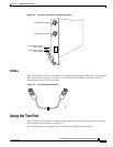
Trunk Card Connectors
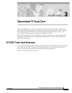
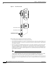
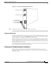
The CT3 front panel is designed with two types of cable connectors (see Figure 3-4). The BNC
connectors are used to connect the cables carrying the T3 signals. The bantam jacks are used for local
BERT circuit testing to the DS1 level.
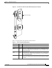
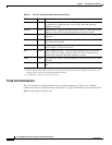
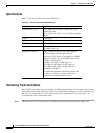
RALM Yellow Remote alarm—Lights to indicate a T1 alarm condition was encountered
by software for a particular port; remains OFF when the operating
condition is normal.
NLOOP Yellow Network loop—Lights to indicate that at least one T1 is unavailable (status
indicator); remains OFF when the operating condition is normal.
T3EN Green
1
Enable—Lights to indicate a CT3 card line connection enabling normal
operation.
T3LOOP
2
Yellow
3
Loopback—Lights to indicate that a loopback condition exists on the CT3
line; software controlled.
LOS Yellow
3
Loss-of-signal—Lights to indicate that the CT3 framer is experiencing a
loss of signal (175 successive zeros).
AIS Yellow
3
Alarm indication signal—Lights to indicate the presence of AIS in the
received CT3 line. Lights to indicate that a T3 alarm condition exists;
remains OFF when the operating condition is normal.
FERF Yellow
3
Far-end receive failure—Lights to indicate a far-end receive failure on the
CT3 line.
OOF Yellow
3
Out-of-frame—Lights to indicate an out-of-frame condition on the CT3
line.
1. This LED must be lit for proper CT3 operation.
2. When in loopback mode, enables diagnostics to perform local CT3 testing without external support. The CT3 line is not
affected by this condition, thus remaining disconnected and open.
3. This LED must remain off for proper CT3 operation.
Table 3-1 CT1/CE1 Trunk Card LED Indicators (continued)
LED Color Description