


4-7
Cisco AS5800 Universal Access Server Dial Shelf Card Guide
78-7097-03 0A
Chapter 4 Double-Density Modem Card
Configuring the Modems
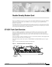
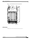
To complete the installation, verify that the CT1/CE1 trunk card LEDs operate properly by observing
the following LED states:
• The power LED is ON.
If the power LED remains OFF, verify that the card is seated properly.
If the power LED lights on other modem cards in the dial shelf, try inserting the CT1/CE1 trunk card
in a different slot. If none of the power LEDs light, check your dial shelf power connections, power
entry modules, and AC-input power supplies (if present).
• The HCPU LED is ON.
If the HCPU LED lights, the CT1/CE1 trunk card has passed diagnostics and the system software is
up and running.
If the HCPU LED is OFF but the power LED is ON, the software image might have failed to load
onto the card. The dial shelf controller attempts to reload the software automatically. If a
programmed number of attempts to reload the software image fails, the dial shelf controller will
power OFF the CT1/CE1 trunk card and the HCPU light will shut off.
Verify that the other cards in the dial shelf work properly. Verify that the card is seated properly. Try
inserting the card in a different slot. Verify that you are using the correct software image by using
the show modem version command.
• The modems LED is ON.
If the modems LED lights, all modem modules present on the card pass diagnostics. You can also
verify modem operation by using the show modem command.
If the modems LED fails to light, you have a faulty CT1/CE1 trunk card. Return the modem card to
the factory for a replacement.
For further installation troubleshooting information, refer to the Cisco AS5800 Universal Access Server
Hardware Installation Guide.
Configuring the Modems
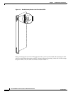
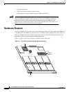
The Cisco 5814 dial shelf is designed to recognize modem cards in slots 0 to 11 within the dial shelf
chassis. If you are installing ten modem cards in the dial shelf chassis, we recommend that you install
modem cards in slots 2 to 11 and reserve slots 0 and 1 for trunk cards.
Note Only slots 0 to 5 are designed to recognize trunk cards and are prioritized for clock
selection, beginning with slot 0. Therefore, you must install trunk cards in the first six slots.
If you are replacing a dial shelf card by installing a new dial shelf card of the same type in the same slot,
the system software recognizes the new dial shelf card interfaces and brings them up automatically. No
additional configuration is needed.
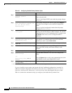
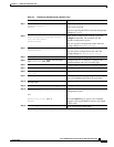
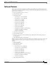
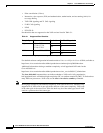
Table 4-3 lists commands to help you configure your double-density modem card.