


5-10
Cisco 2010 Connected Grid Router Hardware Installation Guide
OL-31454-01
Chapter 5 Installing and Upgrading Internal Modules
Installing Grid Router WAN Interface Cards
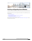
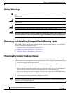
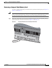
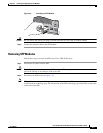
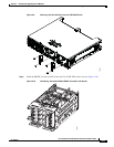
Figure 5-7 Proper Installation of Multiple GRWICs
Step 2
Tighten the three captive screws on the front of the interface card.
Caution For T1/E1 interfaces, shielded cables are required to meet EN55022, Cispr 22, and EN300-386
compliance.
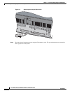
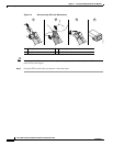
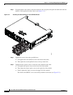
Note When installing multiple GRWICs, the GRWICs must overlap, as shown in Figure 5-8, to ensure a secure
fit.
Figure 5-8 Proper Installation of Multiple GRWICs
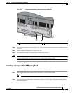
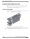
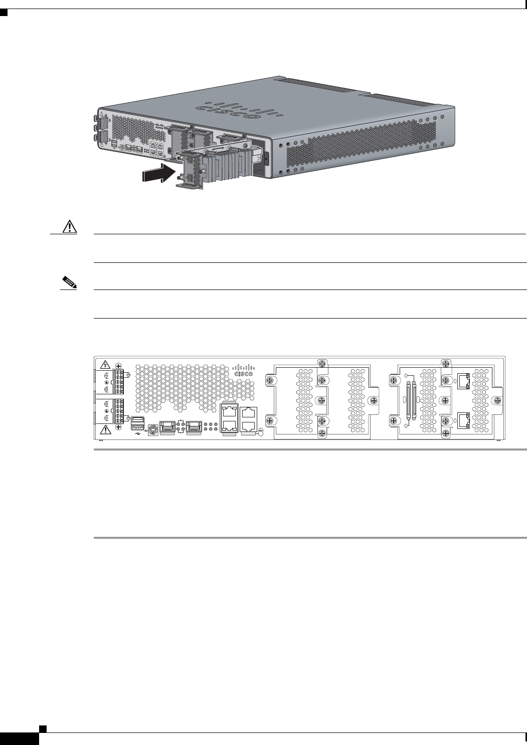
Installing Double-Wide GRWICs
To install the double-wide GRWICs in the Cisco CGR 2010 router:
Step 1 Before you install (or remove) a double-wide GRWIC in the host CGR 2010 router, you must power
down the router as described in the “Shutting Off Power” section on page 3-16.
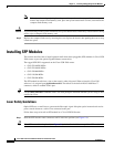
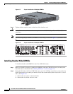
Step 2 Facing the I/O side of the Cisco CGR 2010 router, use a No. 2 Phillips screwdriver to remove the slot
divider between the slots where you intend to install the switch module (either slots 0 and 1 or slots 2
and 3). See Figure 5-9.
a. Remove the two screws on the slot divider.
b. Remove the slot divider and set it aside.
249224
SFP 0/0
SFP 0/1
GE 0/0
GE 0/1
CONSOLE
AUX
EN
EN
Cisco CGR 2010
PSU2PSU1
L
N
N
L
+
Lo
-
-
Lo
+
-
HI
+
+
HI
-
0
1
EN
SPD
CF
1
PS
2
ACT
SYS0
1
SL
SL
SLOT 3 SLOT 2
SLOT 1 SLOT 0
CONN CONN
0-3
4-7
CD/LP AL CD/LP AL
P1 P0
277397
SFP 0/0
GE 0/0
GE 0/1
SFP 0/1
CONSOLE
PSU2
L
N
N
L
+
Lo
-
-
Lo
+
-
HI
+
+
HI
-
Cisco CGR 2010
0
1
EN
EN
SPD
CF
1
PS
2ACT
SYS 0 1
SL
SL
AUX
EN
SLOT 3 SLOT 2 SLOT 1 SLOT 0
CONN CONN
0-3
4-7
GRWIC–8A/8-232
GRWIC–2CE1T1-PRI
CD/LP AL CD/LP AL
P1 P0
PSU1