


3-10
Cisco 2010 Connected Grid Router Hardware Installation Guide
OL-31454-01
Chapter 3 Installing and Connecting the Router
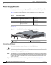
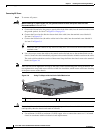
Power-Supply Modules
Connecting AC Power
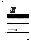
Step 5 To connect AC power:
Warning
When installing or replacing the unit, the ground connection must always be made first and
disconnected last.
Statement 1046
a. Connect the Ground wire (the green or green/yellow lead of the cable) into the terminal marked with
the ground symbol. See item 7 in Figure 3-6 on page 3-9
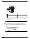
b. Connect the Line wire (the black or brown lead of the cable) into the terminal screw labeled L.
See item 1 in Figure 3-9
c. Connect the Neutral wire (the white or blue lead of the cable) into the terminal screw labeled N.
See item 2 in Figure 3-9
Tip Make sure that you cannot see any wire lead. Only wire with insulation should extend from the
terminal screw.
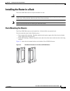
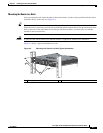
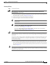
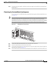
d. Use a tie wrap to secure the cable to the central strain relief tab next to the terminal block on the
chassis. Secure the cable immediately adjacent to the terminal block to minimize strain on the cable.
The strain relief mechanism consists of three metal loops built into the chassis next to the terminal
block. See Figure 3-8
Note Take care not to over-tighten the tie wrap to the loops, which could damage the wiring insulation. An
over-tightened tie wrap could cause cold-flow of the wire insulation, which in turn could cause shorting
of the power source to the chassis.
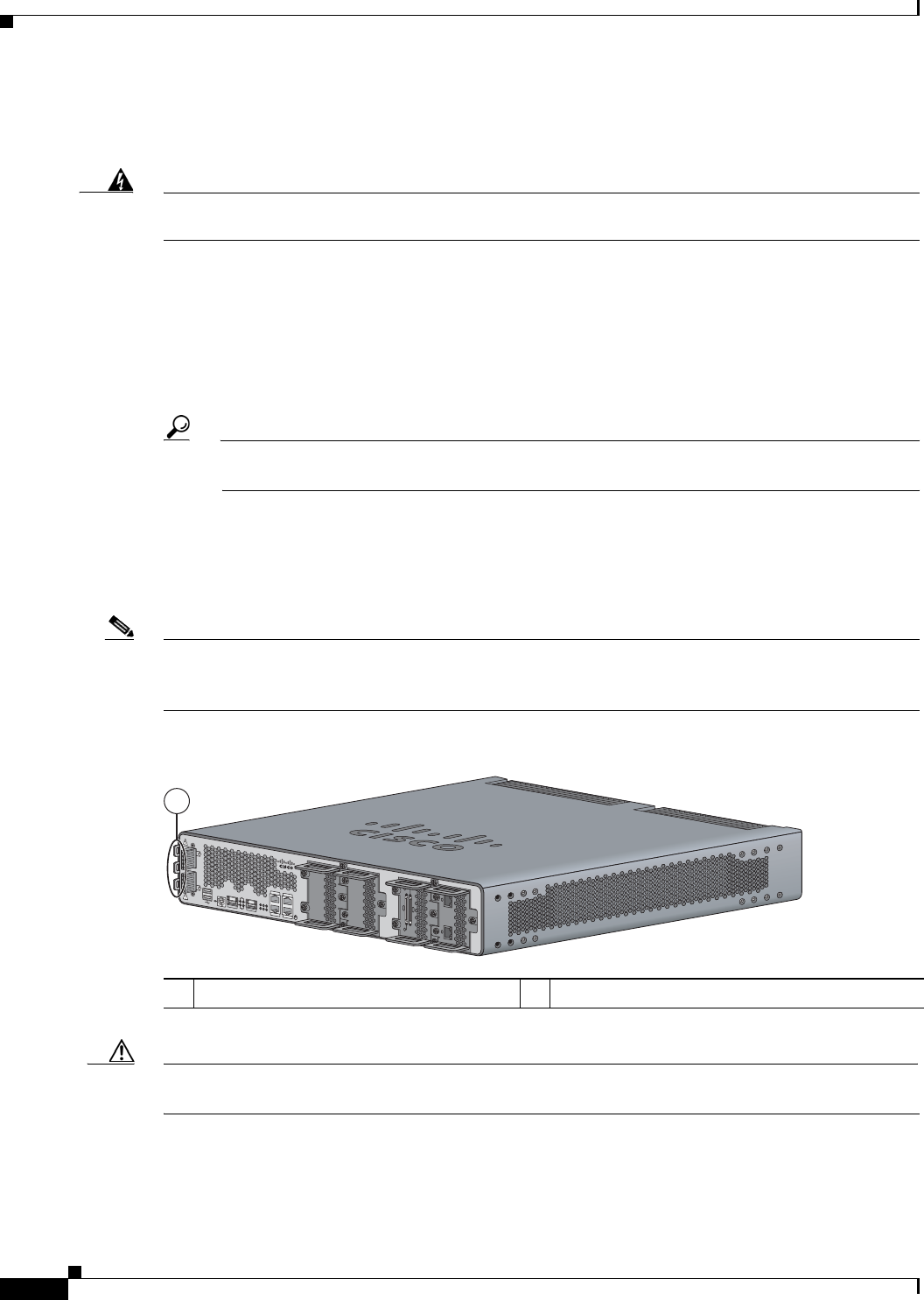
Figure 3-8 Using Tie Wraps with the Strain Relief Mechanism
Caution Ensure that all strands of a stranded wire are properly captured into the terminal block. A loose strand
could possibly short the chassis and result in a hazard.
e. Use minimum 14 AWG or maximum 12 AWG copper wire to connect the router to a 15 A branch
circuit in accordance with local electrical code requirements.
1 Tie wraps to the central strain relief tab.
199587
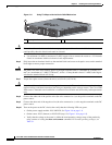
SFP 0/0
SFP 0/1
GE 0/0
GE 0/1
CONSOLE
AUX
EN
EN
Cisco CGR 2010
PSU2PSU1
L
N
N
L
+
Lo
-
-
Lo
+
-
HI
+
+
HI
-
0
1
EN
SPD
CF
1
PS
2
ACT
SYS0
1
SL
SL
SLOT 3 SLOT 2
SLOT 1 SLOT 0
CONN CONN
0-3
4-7
CD/LP AL CD/LP AL
P1 P0
1