


3-31
Cisco 2010 Connected Grid Router Hardware Installation Guide
OL-31454-01
Chapter 3 Installing and Connecting the Router
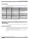
Auxiliary Port, Console Port, and Adapter Pinouts for the Cisco CGR 2010 Router
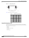
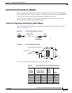
Auxiliary Port Connection to a Modem
In order to connect a PC terminal to the router, use the RJ-45-to-RJ-45 rollover cable and either the
RJ-45-to-DB-25 female DTE adapter or the RJ-45-to-DB-9 female DTE adapter (labeled TERMINAL).
This section lists the pinout descriptions for both DB-9 and DB-25 connections.
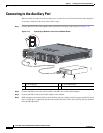
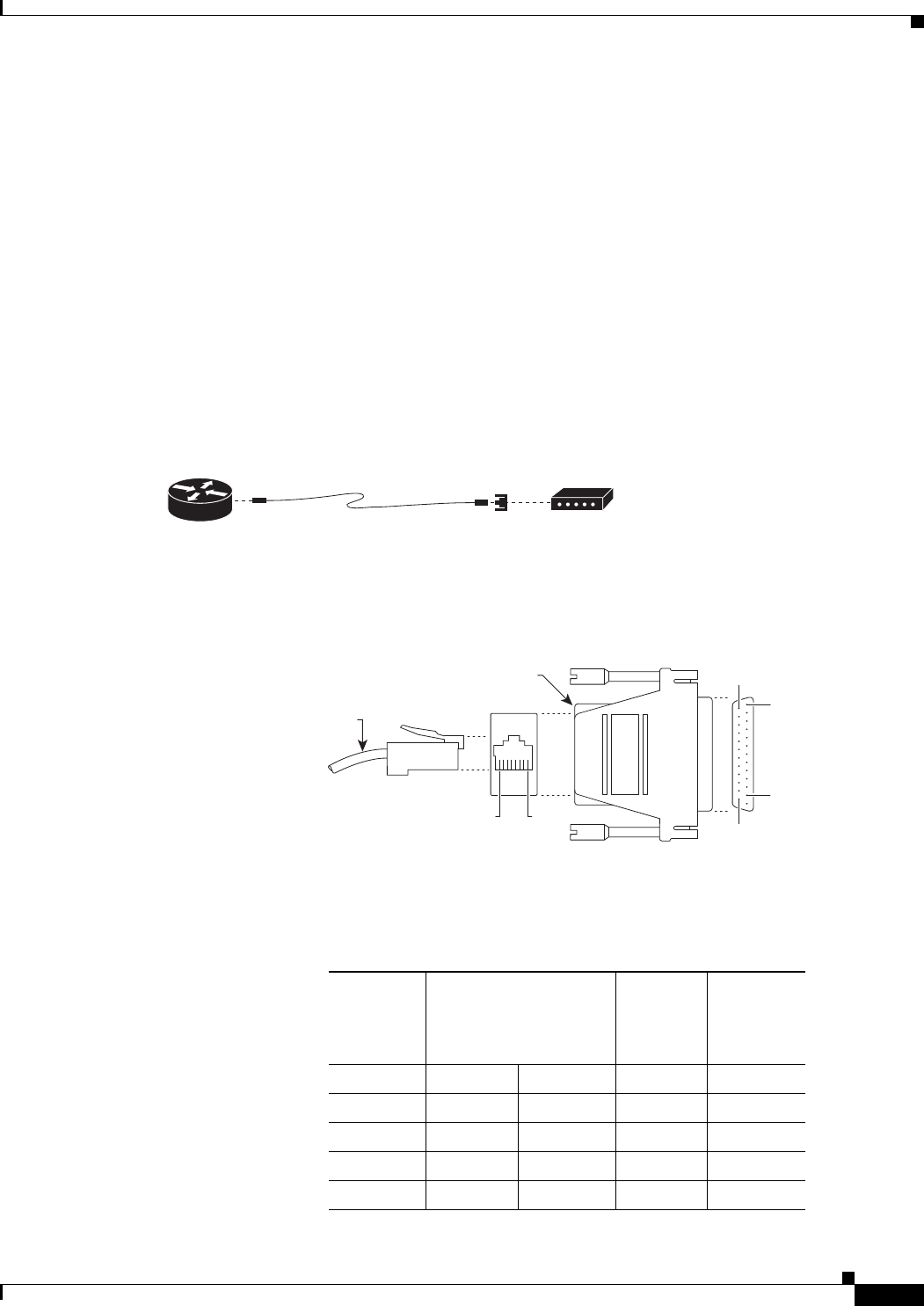
In order to connect a modem to the auxiliary port, use the RJ-45-to-RJ-45 rollover cable and the
RJ-45-to-DB-25 male DCE adapter (labeled MODEM).
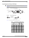
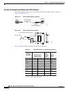
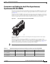
Auxiliary Port Signaling and Cabling Using a DB-25 Adapter
This section describes the auxiliary port signaling and cabling using a DB-25 adapter as shown in
Figure 3-21 and Figure 3-22.
Figure 3-21 RJ-45 to DB-25 Adapter (Terminal)
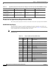
Figure 3-22 RJ-45 to DB-25 Male Adapter
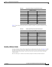
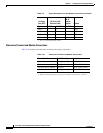
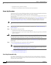
Table 3-9 provides the pinout description for the modem connection:
Modem
RJ-45-to-DB-25
adapter
(labeled Modem)
RJ-45-to-RJ45
roll-over cable
Router
239794
MODEM
CAB-5MODCM
RJ-45 cable
RJ-45-to-DB-25 male adapter
239783
8
1
1
25
13
14
Table 3-9 Pinout Descriptions for the Modem Connection
Auxiliary
Port (DTE)
RJ-45 to RJ-45
Rollover Cable
RJ-45 to
DB-25
Modem
Adapter Modem
Signal RJ-45 Pin RJ-45 Pin DB-25 Pin Signal
RTS 1
1
85CTS
DTR 2 7 6 DSR
TxD 3 6 3 RxD
GND 4 5 7 GND