


3-11
Cisco 2010 Connected Grid Router Hardware Installation Guide
OL-31454-01
Chapter 3 Installing and Connecting the Router
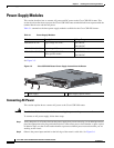
Power-Supply Modules
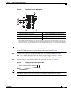
Step 6 Fully insert the un-insulated lead in to the terminal block and screw each captive screw on the terminal
block tight to ensure proper connection.
Caution The AWG size of the wires feeding power to the input terminal block is a minimum of 14 AWG (2.0
mm
2
) or a maximum of 12 AWG (3.309 mm
2
), all for a 15 Amp branch circuit. 12 AWG is the largest
wire that the terminal block will accept.
Step 7 Torque the captive screws (above the wires) to 8.5 in-lb (± 0.5 in-lb).
Caution Stay clear of the terminal block when energy has been restored. The terminal block screw heads and any
exposed wiring could have hazardous line voltages (depending on the voltage source). The Cisco CGR
2010 router is intended to be installed in a restricted access location and serviced by trained personnel
only.
Step 8 Connect the other end of the line wire (the wire connected to L) to the line terminal on the AC power
source.
Step 9 Connect the other end of the neutral wire (the wire connected to N) to the neutral terminal on the AC
power source.
Step 10 Turn on the power at the AC circuit, then verify that the following LEDs are green:
• On the power-supply module: PSU OK LED. See Figure 1-6 on page 1-8
• On the router: PSU1 (bottom) or PSU2 LED (top). See Figure 1-6 on page 1-8
• Verify that the voltage at the router is within the rated operating voltage range of the product by
using a meter or issuing the show environment command. For normal operating voltages, see
Table 3-1
Step 11 If you have two power supplies, install the second power supply in the available slot and repeat Step 1
through Step 10.
Connecting DC Power
This section explains how to connect DC power to the Cisco CGR 2010 router.
Warning
Read the installation instructions before connecting the system to the power source.
Statement 1004
To connect an DC power supply, follow these steps:
Step 1 Verify that power is off to the circuit on the power supply that you are removing. As an added precaution,
place the appropriate safety flag and lockout devices at the source power circuit breaker, or place a piece
of adhesive tape over the circuit breaker handle to prevent accidental power restoration while you are
working on the circuit.
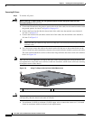
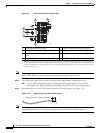
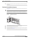
Step 2 Observe the power-input terminal on the left edge of the router’s cable side. See Figure 3-9