


3-35
Cisco 2010 Connected Grid Router Hardware Installation Guide
OL-31454-01
Chapter 3 Installing and Connecting the Router
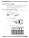
Connectors and Cabling for the 8-Port Asynchronous/ Synchronous RS-232 GRWIC
RS-232 DB-9 Cable Pinouts
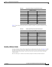
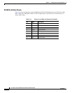
Table 3-13 shows the pinouts for the CAB-9AS-M (High Density 4-port EIA-232 to DB-9, DTE) cable:
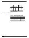
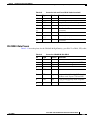
16 — — Unassigned
17 RXC Output Receive Clock
18 LTST Input Loopback Test (also Local Loopback)
19 — — Unassigned
20 DTR Input Data Terminal Ready
21 — — Unassigned
22 — — Unassigned
23 — — Unassigned
24 TXCE Input Transmit Clock Enable
25 — — Unassigned
Table 3-12 Pinouts for Male and Female DB-25 Cables (continued)
Pin Signal Direction Description
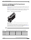
Table 3-13 Pinouts for CAB-9AS-M (Male DB-9)
Pin Signal Direction Description
1— —
2 RD Input Receive Data. Arriving data from DCE.
3 TD Output Transmit Data. Sending data from DTE.
4— —
5 SGND — Ground
6— —
7 RTS Output Request to Send. Raised by DCE when it
wishes to send. Expects CTS from DTE.
8 CTS Input Clear to Send. Raised by DCE in response
to RTS from DTE.
9— —