


3-8
Cisco 2010 Connected Grid Router Hardware Installation Guide
OL-31454-01
Chapter 3 Installing and Connecting the Router
Power-Supply Modules
Power-Supply Modules
This section describes how to connect AC power and DC power to the Cisco CGR 2010 router. This
section also describes how to protect the Cisco CGR 2010 router terminal block from exposure with the
terminal block cover and shut off power.
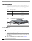
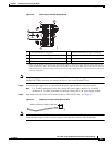
Table 3-1 summarizes the three power-supply modules available for the Cisco CGR 2010 router.
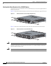
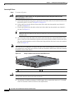
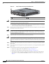
See Figure 3-5.
Figure 3-5 Cisco CGR 2010 Router Power Supply Inserted Into the Router
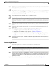
Connecting AC Power
This section explains how to connect AC power to the Cisco CGR 2010 router.
Warning
Read the installation instructions before connecting the system to the power source.
Statement 1004
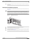
To connect an AC power supply, follow these steps:
Step 1 Verify that power is off to the circuit on the power supply that you are removing. As an added precaution,
place the appropriate safety flag and lockout devices at the source power circuit breaker, or place a piece
of adhesive tape over the circuit breaker handle to prevent accidental power restoration while you are
working on the circuit.
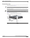
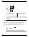
Step 2 Observe the power-input terminal on the left edge of the router’s cable side. See Figure 3-6
Table 3-1 Power-Supply Modules
Model Description Voltage Range
PWR-RGD-AC-DC High-voltage AC or DC. 100-240VAC
100-250VDC
PWR-RGD-LOW-DC Low-voltage DC. 24-60VDC 10 amps
PWR-RGD-AC-DC-C High-voltage AC or DC.
China-specific model.
100-240VAC
100-250VDC
1 Power supply 2 Power supply captive screws
277597
PSU1 PSU2
PSU OK
PWR-150W-HV
SYSSPDSPDSPDSPD 2 0 1USB
CON
ACT
SFP
0/0
EN
SFP
0/1
EN
GE
0/1
LINK
GE
0/0
LINK
PSU
23 1CONSOLE
SLOT
CF1
DO NOT REMOVE DURING
NETWORK OPERATION
CF0
DO NOT REMOVE DURING
NETWORK OPERATION
Cisco 2935R
“CAUTION: This unit may have more than one power source.
Disconnect all power sources before servicing to avoid electric chock.”
PS Type
LoV dc
HiV dc
V ac, 50/60 Hz
10A
2A
2A
Input Rating Per Sources
24-60V
100-270V
100-240V ~
PSU1 PSU2
PSU OK
PWR-150W-HV
SYSSPDSPDSPDSPD 2 0 1
USB
CON
ACT
SFP
0/1
EN
SFP
0/0
EN
GE
0/1
LINK
GE
0/0
LINK
PSU
231
CONSOLE
SLOT
CF1 CF0
PSU OK
PWR-150W-HV
DO NOT REMOVE DURING
NETWORK OPERATION
DO NOT REMOVE DURING
NETWORK OPERATION
Cisco Connected Grid Router 2000 Series
CAUTION: This unit may have more than
one power source. Disconnect all power
sources before servicing to avoid
electric shock.
PSU OK
PWR-150W-HV
2
1
2
PS
Type
Input Terminal
Symbol
Input Rating
Per Source
Lo V DC
Hi V DC
Lo 24 - 60 V 10A
100-250V 2A
100-240V
~
2A
50-60 Hz
Hi
or
V AC
~