


3-6
Cisco 2010 Connected Grid Router Hardware Installation Guide
OL-31454-01
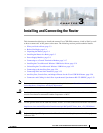
Chapter 3 Installing and Connecting the Router
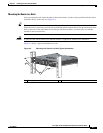
Installing the Router in a Rack
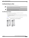
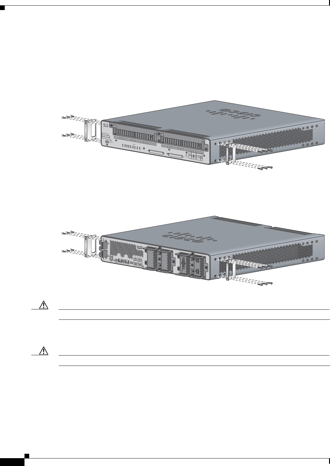
Attaching Rack-Mount Brackets to Cisco CGR 2010 Routers
To attach the long side of each bracket to the Cisco CGR 2010 router, use four of the supplied number-8
Phillips flat-head screws.
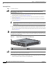
Figure 3-2 shows how to attach the brackets to the sides of the router with the power-supply side forward.
Figure 3-2 Bracket Installation for Power-Supply Side Mounting
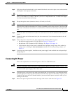
Figure 3-3 shows how to attach the brackets to the sides of the router with the cable-side forward.
Figure 3-3 Bracket Installation for Cable-Side Mounting
Caution Do not over-torque the screws. The recommended torque is 15 to 18 inch-lb (1.7 to 2.0 N-m).
Attach the second bracket to the opposite side of the chassis. Use a number 2 Phillips screwdriver to
install the number-8 bracket screws.
Caution Your chassis installation must allow unrestricted airflow for chassis cooling.
277568
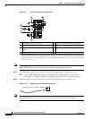
PSU1 PSU2
PSU OK
PWR-150W-HV
SYSSPDSPDSPDSPD 2 0 1
USB
CON
ACT
SFP
0/1
EN
SFP
0/0
EN
GE
0/1
LINK
GE
0/0
LINK
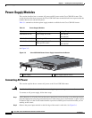
PSU
231
CONSOLE
SLOT
CF1
CF0
PSU OK
PWR-150W-HV
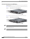
Cisco Connected Grid Router 2000 Series
CAUTION: This unit may have more than
one power source. Disconnect all power
sources before servicing to avoid
electric shock.
DO NOT REMOVE DURING
NETWORK OPERATION
DO NOT REMOVE DURING
NETWORK OPERATION
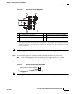
PS
Type
Input Terminal
Symbol
Input Rating
Per Source
Lo V DC
Hi V DC
Lo 24 - 60 V 10A
100-250V 2A
100-240V
~
2A
50-60 Hz
Hi
or
V AC
~
SFP 0/0
SFP 0/1
GE 0/0
GE 0/1
CONSOLE
AUX
EN
EN
Cisco CGR 2010
PSU2PSU1
L
N
N
L
+
Lo
-
-
Lo
+
277447
-
HI
+
+
HI
-
0
1
EN
SPD
CF
1
PS
2
ACT
SYS0
1
SL
SL
SLOT 3 SLOT 2
SLOT 1 SLOT 0
CONN CONN
0-3
4-7
CD/LP AL CD/LP AL
P1 P0