


3-9
Cisco 2010 Connected Grid Router Hardware Installation Guide
OL-31454-01
Chapter 3 Installing and Connecting the Router
Power-Supply Modules
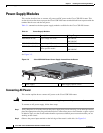
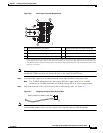
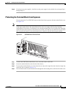
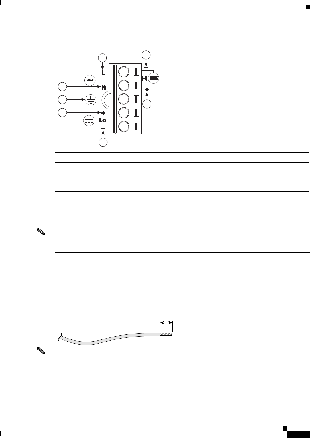
Figure 3-6 Power-Input Terminal Designations
Note The power-supply module 1 connection is labeled PSU1, and the power-supply module 2 connection is
labeled PSU2. Make sure that you connect the wires to the correct terminal screws.
Step 3 Use twisted-pair copper wire to connect from the power-input terminal to the power source.
Note Use 12-AWG (minimum) for the low-voltage DC power supply module. Use 14-AWG
(minimum) or 12-AWG (maximum) for the high-voltage DC or AC power supply module.
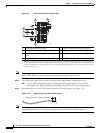
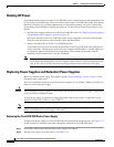
Step 4 Strip each of the two wires to 0.25 inch (6.3 mm) ± 0.02 inch (0.5 mm). See Figure 3-7
Figure 3-7 Stripping the Input Power Source Wire
Note Do not strip more than 0.27 inch (6.8 mm) of insulation from the wire. Stripping more than the
recommended amount of wire can leave exposed wire from the connector after installation.
1 Line connection for AC power
1
1. Please note that the line connection for AC power and the negative connection for high-voltage DC power share the same
power input terminal—that is, this terminal can be used for either AC or DC power. The same is true for the terminal for the
neutral connection for AC power and the positive connection for high-voltage DC power—the same terminal can be used for
either AC or DC power.
4 Positive connection for high-voltage DC
2 Neutral connection for AC power 5 Negative connection for low-voltage DC
3 Negative connection for high-voltage DC 6 Negative connection for low-voltage DC
7 Ground connection
2
7
6
1
3
4
5
PSU2
239311
0.25 in. (6.3 mm)
±
0.02 in. (0.5 mm)
60531