


1-3
Cisco 2010 Connected Grid Router Hardware Installation Guide
OL-31454-01
Chapter 1 Overview of the Router
Hardware Features
Locating Chassis Features and Functions
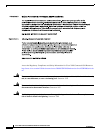
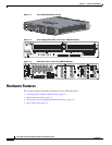
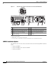
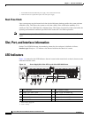
Figure 1-4 shows the different chassis features and functions available on the power supply side view of
the Cisco CGR 2010 router. Figure 1-5 shows the different chassis features and functions available on
the cable side view of the Cisco CGR 2010 router.
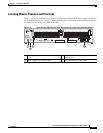
Figure 1-4 Power Supply Side View Features and Functions on the Cisco CGR 2010 Router
248945
PSU1 PSU2
PSU OK
PWR-150W-HV
PSU OK
PWR-150W-HV
SYS SPD SPD SPD SPD 2 0 1
USB
CON
ACT
SFP
0/1
EN
SFP
0/0
EN
GE
0/1
LINK
GE
0/0
LINK
PSU
231
CONSOLE
SLOT
CF1
DO NOT REMOVE DURING
NETWORK OPERATION
CF0
DO NOT REMOVE DURING
NETWORK OPERATION
Cisco Connected Grid Router 2000 Series
CAUTION: This unit may have more than
one power source. Disconnect all power
sources before servicing to avoid
electric shock.
PS
Typ e
Input Terminal
Symbol
Input Rating
Per Source
Lo V DC
Hi V DC
Lo 24 - 60 V 10A
100-250V
2A
100-240V
~
2A
50-60 Hz
Hi
or
V AC
~
1
2
3 4
1 Kensington security slot 2 Caution label and statement for multiple
power source
3 Power supply unit 1 (PSU1) label 4 Power supply power range label