


3-29
Cisco 2010 Connected Grid Router Hardware Installation Guide
OL-31454-01
Chapter 3 Installing and Connecting the Router
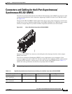
Auxiliary Port, Console Port, and Adapter Pinouts for the Cisco CGR 2010 Router
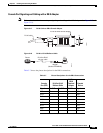
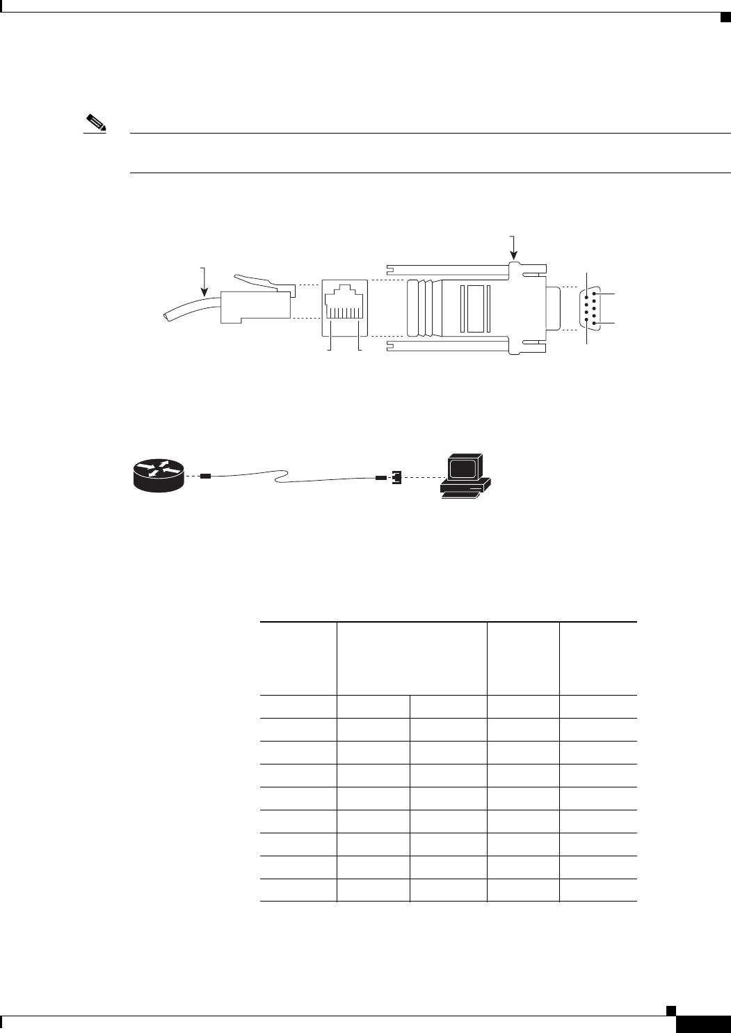
Console Port Signaling and Cabling with a DB-9 Adapter
Note This section describes the console port signaling and cabling with a DB-9 adapter. See Figure 3-17 and
Figure 3-18).
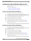
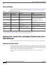
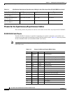
Figure 3-17 RJ-45 Cable to DB-9 Female Adapter
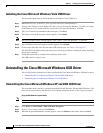
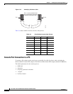
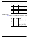
Figure 3-18 RJ-45 to RJ-45 Rollover Cable
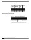
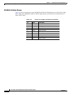
Table 3-7 shows the pinout descriptions for the DB-9 connections:
TERMINAL
9
6
5
1
RJ-45 cable
8
1
RJ-45-to-DB-9 female adapter
239781
PC
RJ-45-to-DB-9
adapter
(labeled TERMINAL)
RJ-45-to-RJ45
roll-over cable
Router
239792
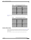
Table 3-7 Pinout Descriptions for the DB-9 Connections
Console
Port (DTE)
RJ-45 to RJ-45
Rollover Cable
RJ-45 to
DB-9
Terminal
Adapter
Console
Device
Signal RJ-45 Pin RJ-45 Pin DB-9 Pin Signal
RTS 1
1
1. Pin 1 is connected internally to Pin 8.
88CTS
DTR 2 7 6 DSR
TxD 3 6 2 RxD
GND 4 5 5 GND
GND 5 4 5 GND
RxD 6 3 3 TxD
DSR 7 2 4 DTR
CTS 8 1 7 RTS