


3-16
Cisco 2010 Connected Grid Router Hardware Installation Guide
OL-31454-01
Chapter 3 Installing and Connecting the Router
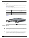
Power-Supply Modules
Shutting Off Power
Even though shutting off power to the Cisco CGR 2010 router is anticipated to be infrequent, there may
be occasion to turn off the router. There is no on/off switch on the Cisco CGR 2010 router. This ensures
that there will not be any accidental shutdown due to inadvertently turning off a power switch; thus,
guaranteeing a high reliability in keeping the router up. To shut off power to the router, there are two
options:
• Pull the power supply modules out of the Cisco CGR 2010 router. See “Replacing Power Supplies
and Redundant Power Supplies” section on page 3-16.
The power supplies on the Cisco CGR 2010 router are hot swappable, so merely removing them
from the router will remove power from the router and shut it down.
• Install a disconnect device for the Cisco CGR 2010 router.
A disconnect device must be located in the proximity of the Cisco CGR 2010 router and must be
readily accessible. The disconnect device must also comply with IEC 60947-1 and IEC 60947-3 or
an equivalent approved disconnect device appropriate for the country of installation and be
identified as the disconnect device for this equipment.
Note The maximum current rating for the power disconnect circuit breaker or overcurrent device must
be 15 Amps. Operational power must be internally fused. This fuse cannot be replaced by the
user. In the event of the disconnect device failing, return the unit to the factory for repair.
Replacing Power Supplies and Redundant Power Supplies
Before you perform power supply replacement, read the “Safety Warnings” section on page 5-2 and
disconnect power when noted.
The Cisco CGR 2010 routers have replaceable power supplies. Use a Number 2 Phillips screwdriver to
remove or install the power supply.
Caution Any combination of power supplies can be inserted into the chassis. Dual power supply configurations
are load sharing in redundancy mode.
A single power supply is sufficient for supporting power needs to the system. A single PSU can be
deployed in either slot 1 (PSU1) or slot 2 (PSU2).
Note The power supplies are hot swappable. The power supply LED must show it is properly functioning
before removing the other power supply in the router.
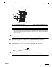
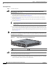
Replacing the Cisco CGR 2010 Router Power Supply
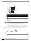
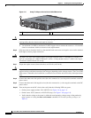
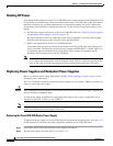
To replace the power supply in a Cisco CGR 2010 router, perform the following steps. See Figure 3-13
for the locations of connectors and other components within the Cisco CGR 2010 router.
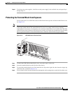
Step 1 Loosen the captive screws that fasten the power supply to the chassis.
Step 2 Pull the power supply out of the chassis. See Figure 3-13.