


1-8
Cisco 2010 Connected Grid Router Hardware Installation Guide
OL-31454-01
Chapter 1 Overview of the Router
Slot, Port, and Interface Information
Real-Time Clock
Upon system power up, the internal real-time clock with battery backup provides the system software
with time of day. This allows the system to verify the validity of the certification authority (CA)
certificate. The Cisco CGR 2010 has a lithium battery. This battery lasts the life of the router under the
operating environmental conditions specified for the router and is not field-replaceable.
Note If the lithium battery in a Cisco CGR 2010 router should fail, the router must be returned to Cisco for
repair.
Slot, Port, and Interface Information
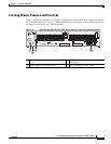
On the Cisco CGR 2010 router, the numbering format for slots and ports is defined as follows:
interface type 0/slot/port. “0” indicates slots that are built into the chassis of a router.
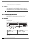
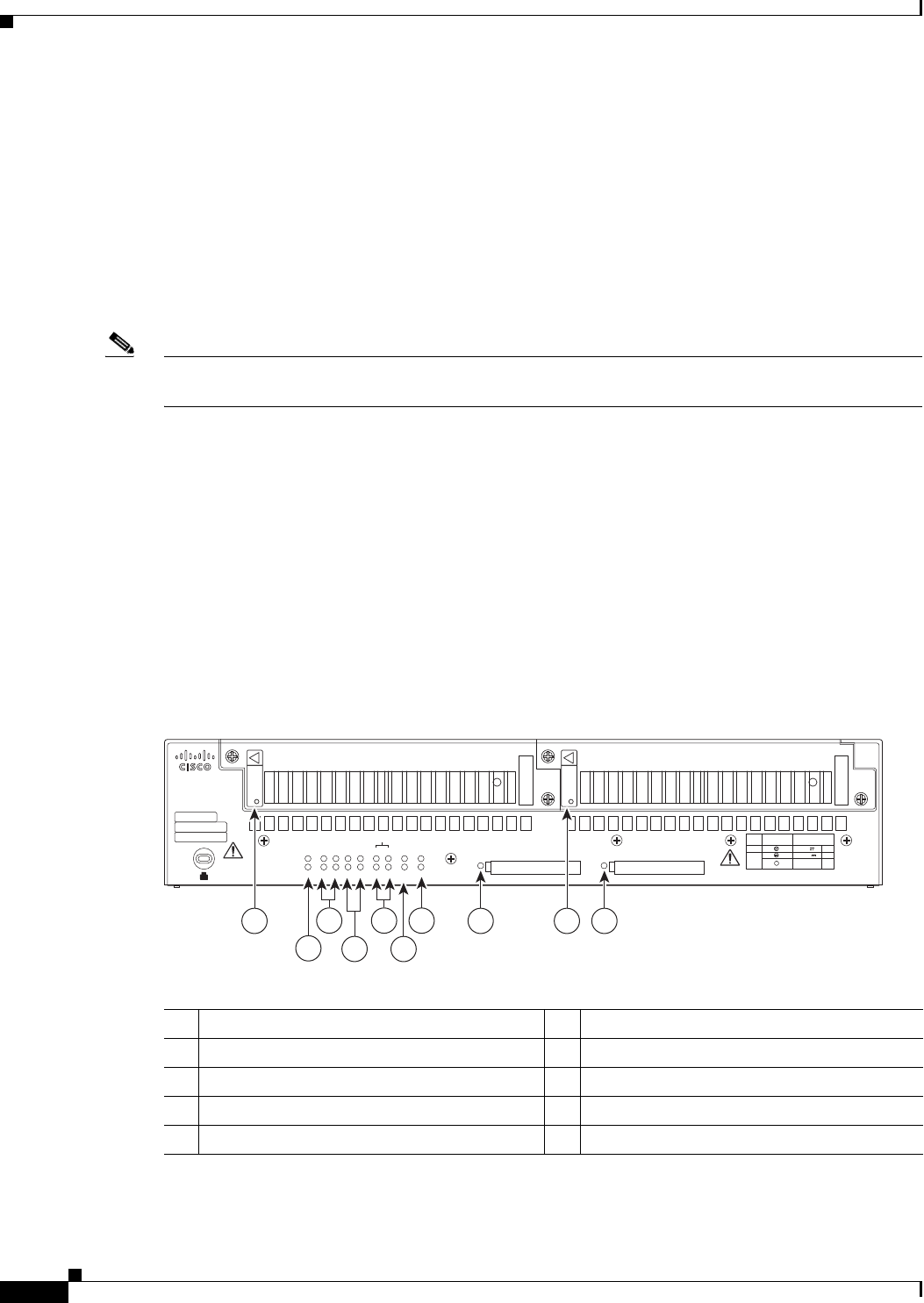
LED Indicators
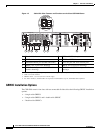
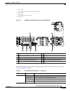
Figure 1-6 summarizes the LED indicators that are located on the router bezel or chassis, but not on the
removable interface cards.
Figure 1-6 Power Supply Side View LEDs on the Cisco CGR 2010 Router
1. Internal RPS means that additional power supply can be added to the PS2 slot.
2. Dual DC means two separate DC inputs to the same power supply.
277566
PSU1 PSU2
PSU OK
PWR-150W-HV
PSU OK
PWR-150W-HV
SYS SPD SPD SPD SPD 2 0 1
USB
CON
ACT
SFP
0/1
EN
SFP
0/0
EN
GE
0/1
LINK
GE
0/0
LINK
PSU
231
CONSOLE
SLOT
CF1
DO NOT REMOVE DURING
NETWORK OPERATION
CF0
DO NOT REMOVE DURING
NETWORK OPERATION
Cisco Connected Grid Router 2000 Series
CAUTION: This unit may have more than
one power source. Disconnect all power
sources before servicing to avoid
electric shock.
PS
Typ e
Input Terminal
Symbol
Input Rating
Per Source
Lo V DC
Hi V DC
Lo 24 - 60 V
10A
100-250V
2A
100-240V
~
2A
50-60 Hz
Hi
or
V AC
~
1 98
2
10
6
7
3
4
5
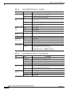
1 PSU
1
OK LED
1. PSU = Power supply unit
2 ACT
2
and SYS
3
LEDs
2. ACT = Activity
3 SFP0/1
4
EN
5
SPD
6
LEDs 4 GE0/1
7
LNK
8
and SPD LED
5 SLOT LEDs (slots 0 through 3) 6 Console/USB connection LEDs
7 PSU1/2 LEDs 8 Compact flash slot 1 LED
9 PSU OK LED 10 Compact flash slot 0 LED