


3-28
Cisco 2010 Connected Grid Router Hardware Installation Guide
OL-31454-01
Chapter 3 Installing and Connecting the Router
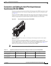
Auxiliary Port, Console Port, and Adapter Pinouts for the Cisco CGR 2010 Router
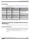
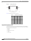
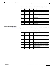
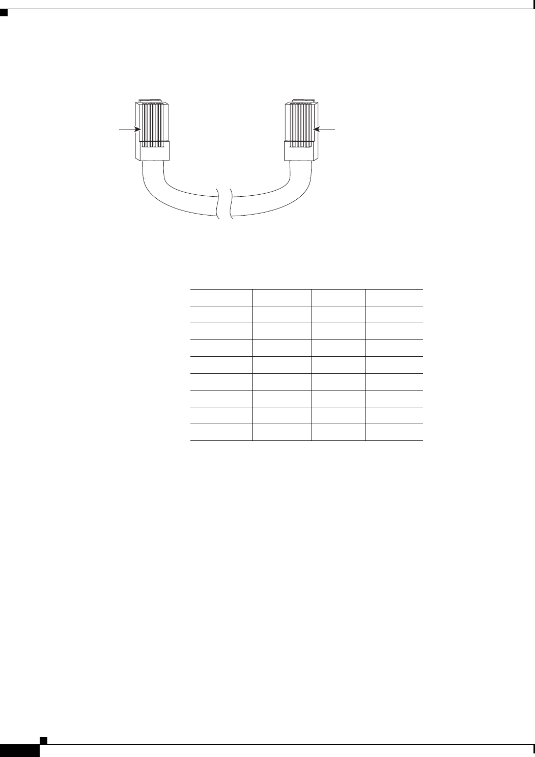
Figure 3-16 Identifying a Rollover Cable
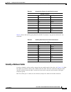
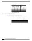
Table 3-6 shows the RJ-45 rolled (console) cable pinouts:
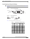
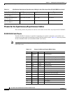
Console Port Connection to a PC
To connect a PC terminal to the console port, use the RJ-45-to-RJ-45 rollover cable, and either the
RJ-45-to-DB-25 female DTE adapter or the RJ-45-to-DB-9 female DTE adapter (labeled TERMINAL).
The default parameters for the console port are:
• 9600 baud
• 8 data bits
• No parity generated or checked
• 1 stop bit
• No Flow Control
Pin 1
239780
Pin 8
Pin 1 on one connector and
pin 8 on the other connector
should be the same color.
Table 3-6 RJ-45 Rolled Console Cable Pinouts
Signal Pin Pin Signal
-18-
-27-
-36-
-45-
-54-
-63-
-72-
-81-