


6-11
Cisco Content Services Switch Routing and Bridging Configuration Guide
OL-4580-01
Chapter 6 Configuring the Internet Protocol
Configuring IP Opportunistic Layer 3 Forwarding
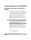
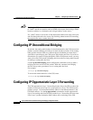
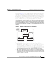
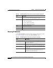
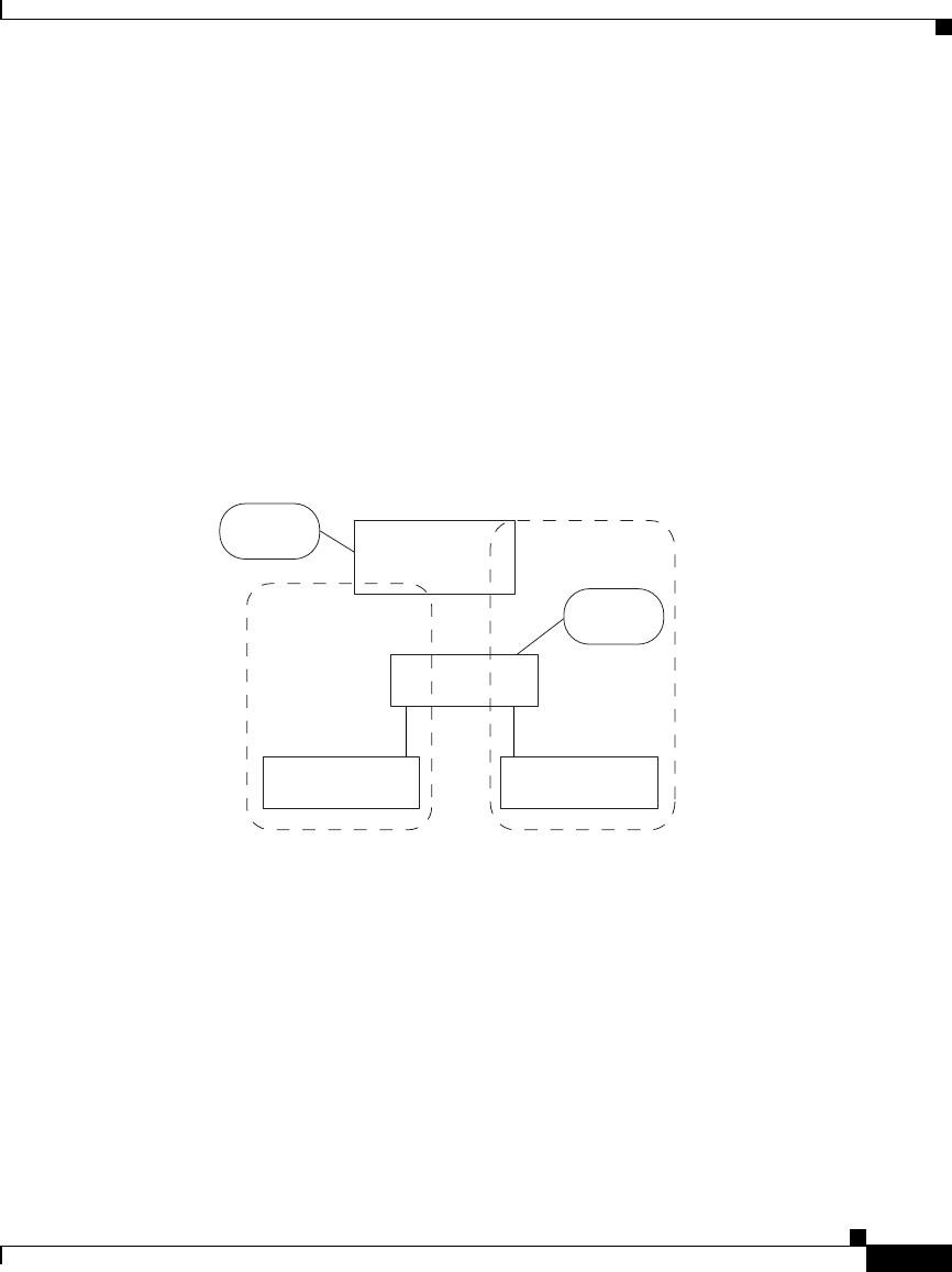
For example, Figure 6-1 shows a CSS connected to VLAN1 and VLAN2. Each
VLAN has an end station and an uplink to Router1. End stations A and B both
point to Router1 as their default router. When End Station A transmits a packet to
End Station B, it uses its default route to Router1. The packet contains Router1’s
destination MAC address. A traditional Layer 2 device forwards the packet to
Router1, and Router1 forwards the packet to End Station B on VLAN2.
Using opportunistic Layer 3 forwarding, the CSS inspects the IP packet header to
determine the destination IP address. Instead of forwarding the packet to Router1,
the CSS forwards the packet directly to End Station B. Because the CSS handles
the packet only once, the router and uplink are not used and network resources are
conserved.
Figure 6-1 Example of Opportunistic Layer 3 Forwarding
The options for this global configuration mode command are as follows:
• local (default) - Applies opportunistic Layer 3 forwarding if the destination
IP address belongs to a node that resides on one of the subnets directly
attached to the CSS and the CSS is aware of an ARP resolution for that node.
Because the local option is the default, use the no ip opportunistic command
to reconfigure IP opportunistic Layer 3 forwarding to the local setting.
• all - Applies opportunistic Layer 3 forwarding if the destination IP address
matches any entry in the CSS routing table. We do not recommend this option
if the topology includes multiple routers and the CSS does not know all of the
routes the routers are aware of.
End Station A
Subnet
VLAN2
VLAN1
Router1
(default)
End Station B
CSS
Internet
49383