Compaq Deskpro 2000 Series of Personal Computers 1-5
■
Mouse
■
Keyboard and mouse connectors on the back panel
■
Internal piezo speaker mounted on system board
■
Intelligent Manageability and security features, including password and cable lock provision
■
Compaq Diagnostics and Configuration utilities, support software, and device drivers
1.3 System Design
This section presents a design overview and functional descriptions of the key components of the
Compaq Deskpro 2000 Series of Personal Computers. All replaceable components are identified in
Chapter 3, and removal/replacement instructions are presented in Chapters 5 and 6.
1.3.1 Design Overview
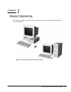
The desktop models of the Compaq Deskpro 2000 Series of Personal Computers have a conventional
design that uses a pan-type chassis to house the system board, expansion cards, power supply, and
mass storage devices. The chassis is supplemented by a riser board attached to the riser brace. The
riser board provides a mounting location for the expansion cards.
All internal components are accessible when the hood, held in place by two thumbscrews, is
removed. The front bezel is mounted to the front of the chassis. Torx T-15 screws are used
throughout the system.
The system board is easily removed from the side of the chassis after the hood and riser board are
removed. Details of the disassembly procedure for desktop models are found in Chapter 5, “Removal
and Replacement Procedures.”
The riser board mounts perpendicularly to the system board. Expansion boards are installed
horizontally into the riser board. A single screw attaches each expansion board to the rear panel of the
chassis.
The power supply is mounted in the right rear corner of the chassis. The power supply is held in
place by three Torx screws that are installed through the rear panel of the chassis.
The minitower models have a chassis designed to house the system board, riser board, option cards,
power supply, and mass storage devices. The use of a riser brace to hold the riser board, and any
expansion boards installed, allows for easy access to the system board. The power supply is mounted
in the top of the unit.
All internal components are immediately accessible when the side panel is removed.
The minitower’s tray-mounted system board is easily removed after taking off the side panel and
riser brace. Details of the disassembly procedure for minitower models are found in Chapter 6,
“Removal and Replacement Procedures.”
Detailed descriptions of the system components are presented in the sections that follow.


